Object counter and method for counting objects

a technology which is applied in the field of object counter and object counting method, can solve the problems of limiting the use of the method to devices with a lot of spare processing power, objects being close together, and/or having approximately the same speed, and achieving the effect of facilitating counting moving objects and reducing the bandwidth requirement of the system

Active Publication Date: 2012-05-24
AXIS
View PDF1 Cites 24 Cited by
  • Summary
  • Abstract
  • Description
  • Claims
  • Application Information

AI Technical Summary

Benefits of technology

[0021]This object counter facilitates counting moving objects in a processing environment having limited capacity, e.g., processing capacity, storing capacity, etc. One reason for this results from the fact that the object counter includes a contribution zone calculator and an area calculator making the object counter operate on area flow, i.e., sub areas within a motion region, and therefore there is no need for processing intensive means such as identity critical object trackers.
[0022]In one embodiment, the object counter is arranged in a camera. Thereby the bandwidth requirement of the system may be decreased, because no images are required to be sent over the network for the people counter functionality.

Problems solved by technology

One problem with the current object detection algorithms is that objects being close together, having similar features, and / or having approximately the same speed are very difficult to detect as separate objects.
The problem occurs because the cluster of objects may be detected as one single object.
Many object counters rely on simply counting the detected objects which will result in an underestimation of the number of objects if the objects arrive in clusters and if each cluster is counted as one object.
However, such shape analysis of the detected objects requires a lot of processing power, hence, limiting the use of the method to devices having a lot of spare processing power.
Such processing power may not be available in embedded systems or devices having small form factor.
However, when moving objects passing a boundary are to be counted, this method is not reliable.

Method used


Image

  • Object counter and method for counting objects
  • Object counter and method for counting objects
  • Object counter and method for counting objects

Examples


Embodiment Construction

[0040]Before the invention is described in detail, it is to be understood that this invention is not limited to the particular component parts of the device described or steps of the methods described, as such device and method may vary. It is also to be understood that the terminology used herein is for purpose of describing particular embodiments only, and is not intended to be limiting. It must be noted that, as used in the specification and the appended claim, the articles “a”, “an”, “the”, and “said” are intended to mean that there are one or more of the elements unless the context clearly dictates otherwise. Thus, for example, reference to “a sensor” or “the sensor” may include several sensors, and the like. Furthermore, the word “comprising” does not exclude other elements or steps. Moreover, in the figures like reference characters designate like or corresponding parts throughout the several figures.

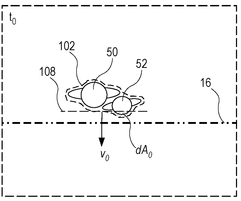
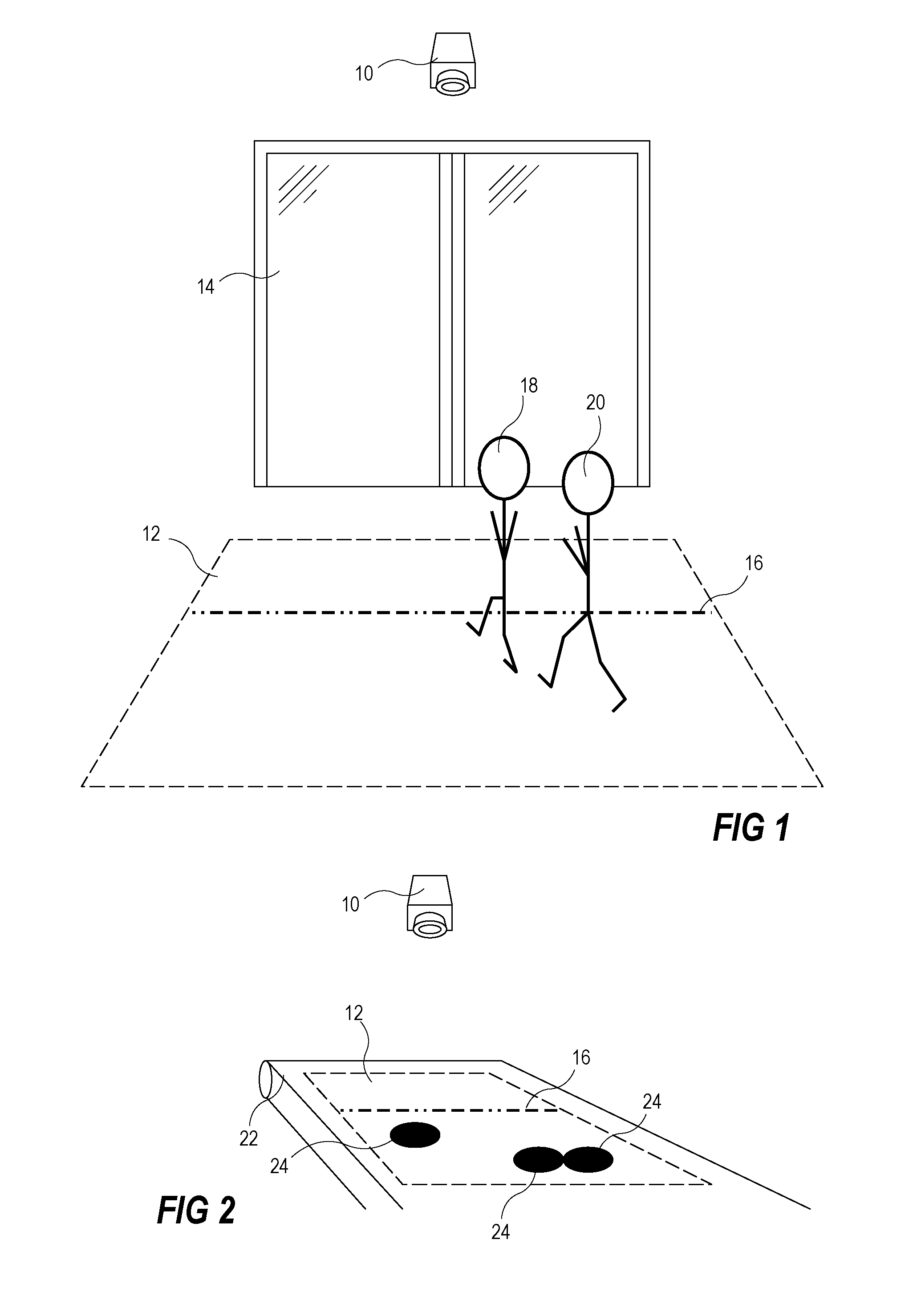
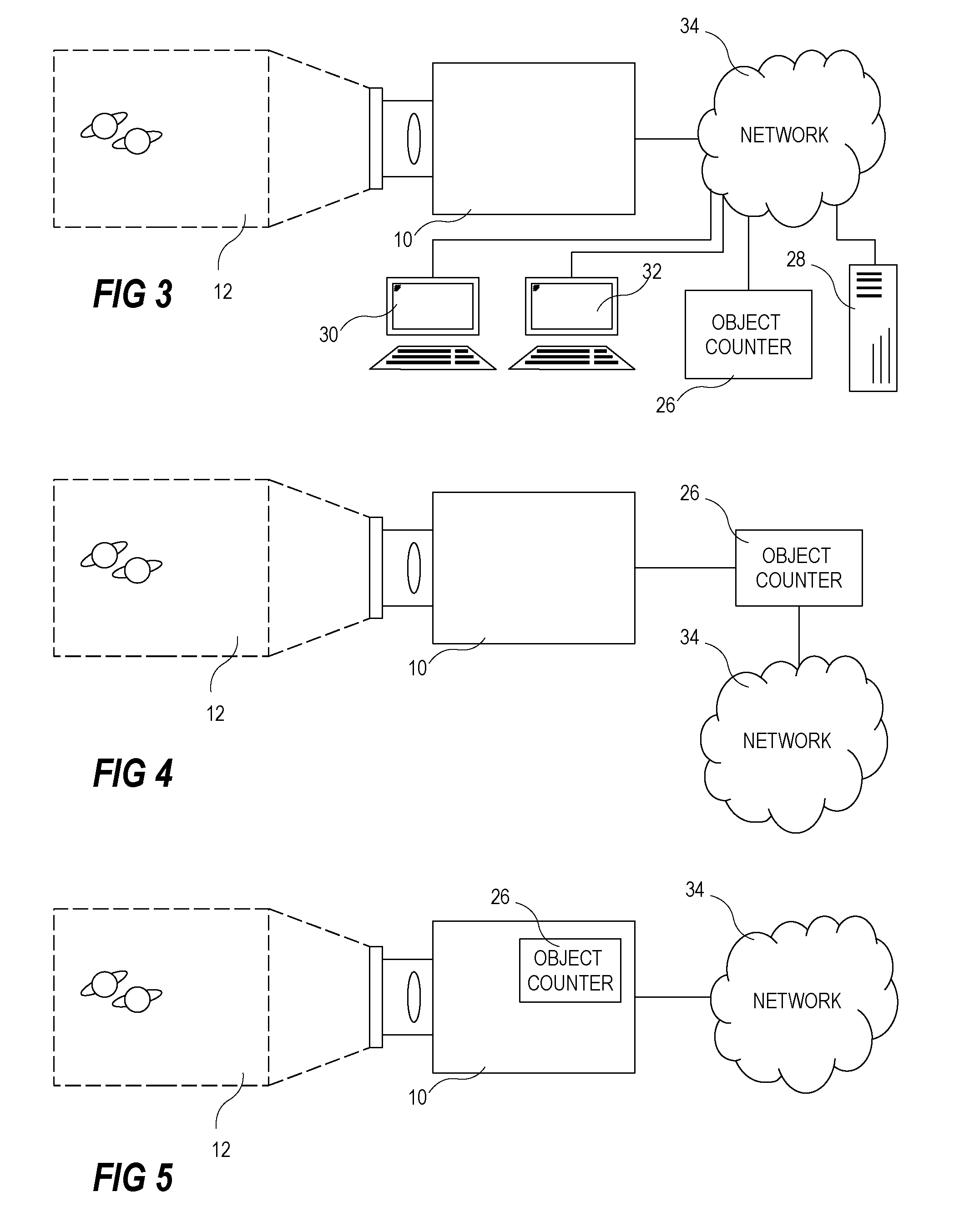
[0041]The present invention is related to the task of counting objects. Meth...


PUM


Abstract

An object counter performs a method for counting objects that includes capturing images representing moving images of a predetermined counting view, detecting a motion region in the moving images of the predetermined counting view, calculating a motion region speed value indicating a speed of movement of the motion region. A contribution zone is repeatedly defined based on a predetermined counting boundary, the motion region speed value, and a contribution time period. A sub area value representing the size of the area of the motion region contained in the defined contribution zone is repeatedly retrieved and registered. A total area value is generated by adding a plurality of registered sub area values, and estimating the number of objects that have passed the counting boundary based on a reference object area value.

Description

CROSS REFERENCE TO RELATED APPLICATIONS[0001]This application claims priority to U.S. Provisional Application No. 61 / 415,134 filed on Nov. 18, 2010 and European Patent Application 10191650.0 filed on Nov. 18, 2010, which are incorporated by reference as if fully set forth.TECHNICAL FIELD OF THE INVENTION[0002]The present invention relates to an object counter and a method for counting objects passing a predetermined boundary. More particularly it relates to counting such objects by means of analyzing images captured using a camera.BACKGROUND OF THE INVENTION[0003]Object counters based on a sensor and an analyzer cooperating for determining the number of objects passing a boundary is widely used in different applications.[0004]An object counter is a device which is used to count objects, like for example people entering or leaving a department store, a train station or any other area of interest, livestock leaving or entering an area, products passing on a conveyor belt, or products ...

Claims


Application Information

Patent Timeline
Patent Type & Authority Applications(United States)
IPC IPC(8): G06K9/00
CPCG06T7/2053G06T7/20G06T2207/30196G06T2207/10016G06T7/254G06T7/579G06T7/246
Inventor ALMBLADH, JOHAN
Owner AXIS
Why Eureka
Try Eureka