
Anti-shake device and optical system having the same

an anti-shake device and optical system technology, applied in the field of anti-shake devices for use in optical systems, can solve the problems of blurred images, inability to form images stably, and very likely shaken optical paths, etc., and achieves the effects of simple structure, easy assembly and small volum

Active Publication Date: 2012-05-24
TDK TAIWAN
View PDF0 Cites 49 Cited by
  • Summary
  • Abstract
  • Description
  • Claims
  • Application Information

AI Technical Summary

Benefits of technology

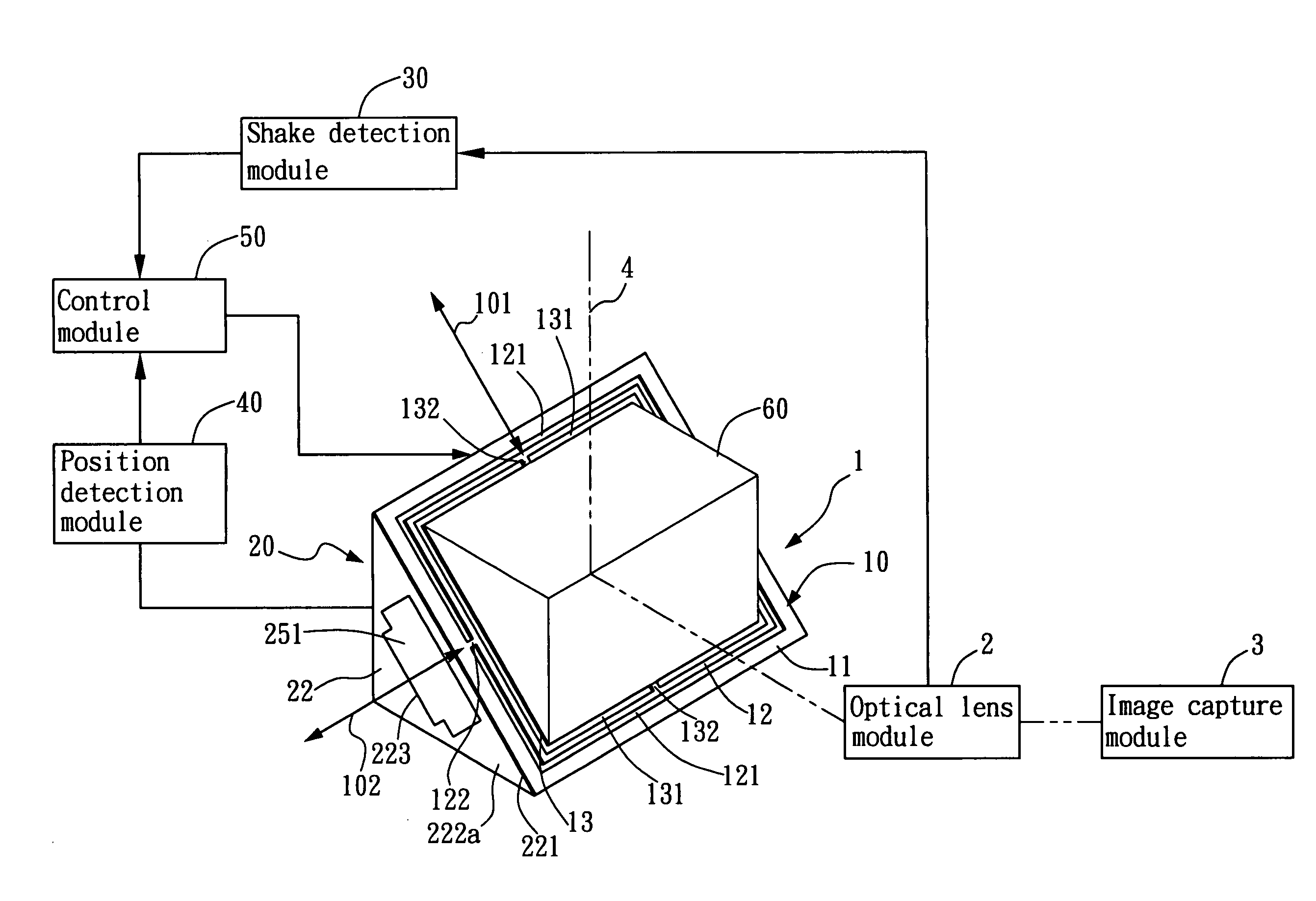
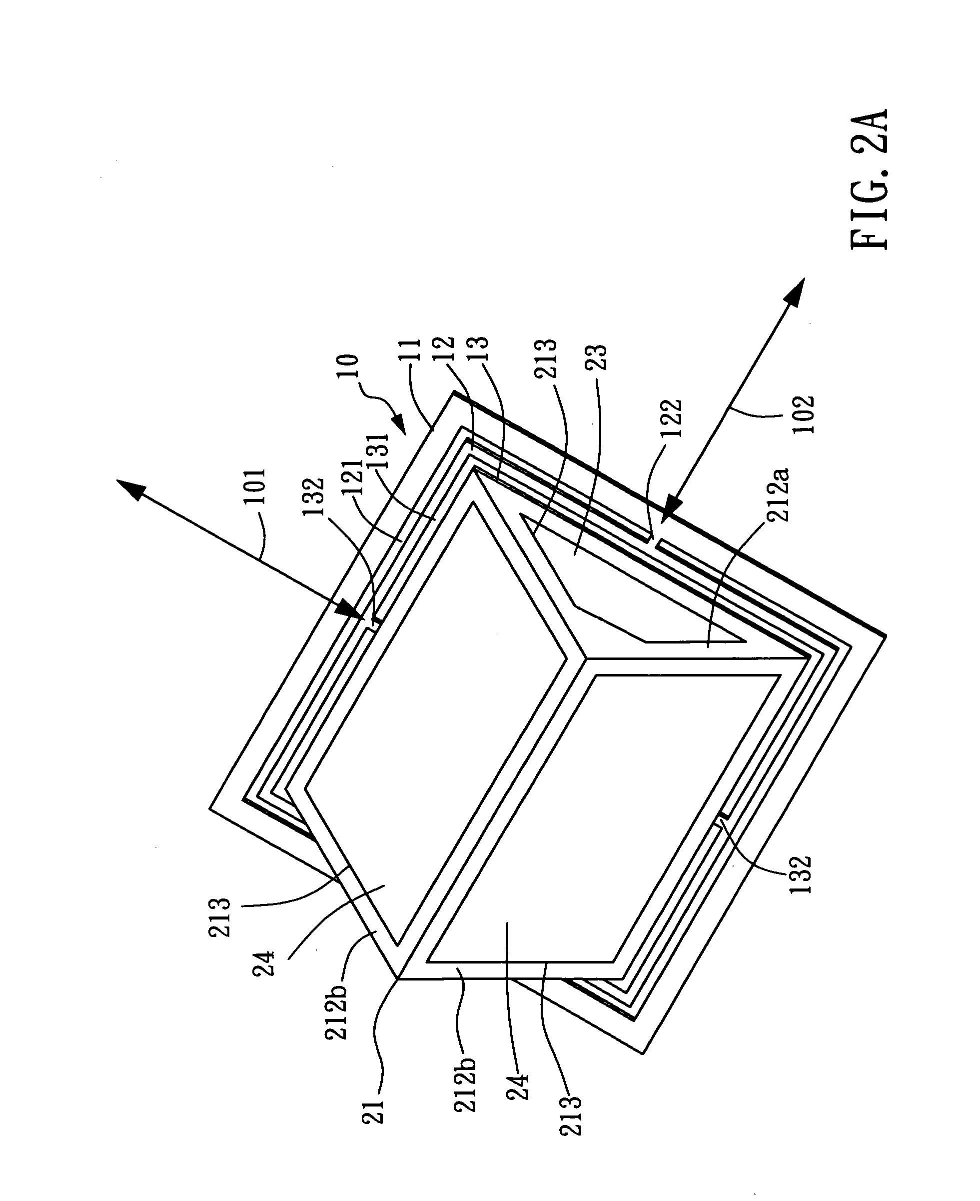
[0006]The first object of the present invention is to provide an anti-shake device to be installed in an optical system, wherein a biaxial rotating element having a special multiple-frame structure is formed by making grooves in a thin resilient plate and is driven by a driving module to pivot about two axes to a limited extent. Thus, the anti-shake device features a simple structure, is easy to assemble, has a small volume, and incurs low cost.
[0007]The second object of the present invention is to provide an anti-shake device for use in an optical system, wherein an electromagnetic driving device composed of permanent magnets and coils drives a biaxial rotating element to pivot about two axes to a limited extent, and wherein the permanent magnets and the coils are mounted on and positioned by structurally unique inner and outer support frames. Thus, the anti-shake device features a simple structure, is easy to assemble, has a small volume, and incurs low cost.
[0028]a control module connected to the shake detection module, the position detection module, and the driving module and configured to control the driving module according to the shake amount of the optical lens module, detected by the shake detection module, and the amounts by which the biaxial rotating element is pivoted, detected by the position detection module, so that the driving module pivots the biaxial rotating element and thereby compensates for an unstable state of the optical path that is caused by shaking of the optical lens module.

Problems solved by technology

In an optical system composed of an optical lens set and an image capture module, such as a camera for taking still and / or moving images, the optical path is very likely to be shaken or shifted by an external force or by the shaking of hands holding the camera.
Once the optical path is shaken, the image capture module is unable to form images stably, and the images thus taken are blurred.
However, the existing optical anti-shake mechanisms typically require complicated or bulky structures or elements and therefore leave much room for improvement, particularly in terms of technical complexity, the difficulty of assembly, cost, and volume.

Method used


Image

  • Anti-shake device and optical system having the same
  • Anti-shake device and optical system having the same
  • Anti-shake device and optical system having the same

Examples


Embodiment Construction

[0036]The present invention provides an anti-shake device for use in an optical system, and the principle on which the anti-shake device works is stated as follows. A biaxial rotating element having a special multiple-frame structure is formed by grooving a thin resilient plate. The biaxial rotating element, when driven by an electromagnetic driving module, makes limited pivotal movement about two axes so as to provide shake compensation. The electromagnetic driving module, composed of a plurality of permanent magnets and a plurality of coils, is supported and positioned by an inner support frame and an outer support frame, both of which have uniquely designed structures. The resultant anti-shake device is structurally simple, easy to assemble, compact in size, and relatively low-cost.

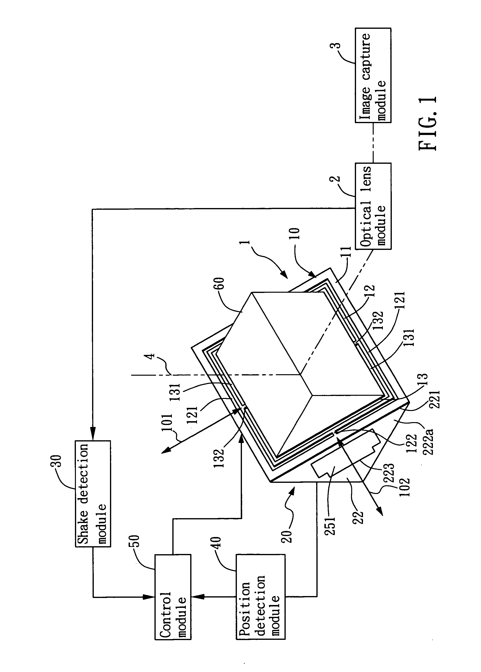
[0037]Please refer to FIGS. 1 through 4 for a preferred embodiment of the disclosed anti-shake device for use in an optical system.

[0038]As shown in FIG. 1, an anti-shake device 1 according to the pres...


PUM


Abstract

An anti-shake device for use in an optical system comprises a biaxial rotating element and a electromagnetic driving module. The biaxial rotating element is made by grooving a thin resilient plate to form a special multiple-frame structure. The biaxial rotating element, when driven by the electromagnetic driving module, makes limited pivotal movement about two axes so as to provide shake compensation. The electromagnetic driving module, composed of a plurality of permanent magnets and a plurality of coils, is supported and positioned by an inner support frame and an outer support frame, both of which have uniquely designed structures. The resultant anti-shake device is structurally simple, easy to assemble, compact in size, and relatively low-cost.

Description

BACKGROUND OF INVENTION[0001]1. Field of the Invention[0002]The present invention relates to an anti-shake device for use in an optical system. More particularly, the present invention relates to an anti-shake device and an optical system using the same, wherein the anti-shake device includes a biaxial rotating element which is formed of a thin resilient plate and driven by an electromagnetic driving module to pivot about two different axes and thereby compensate for the unstable state of the optical path of the optical system while the optical system is shaken.[0003]2. Description of the Prior Art[0004]In an optical system composed of an optical lens set and an image capture module, such as a camera for taking still and / or moving images, the optical path is very likely to be shaken or shifted by an external force or by the shaking of hands holding the camera. Once the optical path is shaken, the image capture module is unable to form images stably, and the images thus taken are blu...

Claims


Application Information

Patent Timeline
IPC IPC(8): G03B17/00G02B27/64
CPCG02B27/646G03B5/00G03B2205/0023G03B2205/0069G03B5/06
Inventor HU, CHAO CHANG
Owner TDK TAIWAN
Learn More