Cleaning member

a cleaning member and flexible technology, applied in the direction of optics, instruments, electrographic processes, etc., can solve the problem of narrow setting image in which cleaning is satisfactorily performed, and achieve the effect of stable cleaning

Inactive Publication Date: 2012-05-24
CANON KK
View PDF3 Cites 2 Cited by
  • Summary
  • Abstract
  • Description
  • Claims
  • Application Information

AI Technical Summary

Benefits of technology

[0004]The present invention has been accomplished in view of the circumferences described above. A principal object of the present invention is to provide a small-sized cleaning member capable of realizing stable cleaning.

Problems solved by technology

However, particularly in the case where the above-described toner which has been downsized and sphered is used, the toner is liable to pass through the cleaning member and therefore such a problem that a setting image in which the cleaning is satisfactorily performed is narrow occurs.

Method used


Image

  • Cleaning member
  • Cleaning member
  • Cleaning member

Examples


embodiment 1

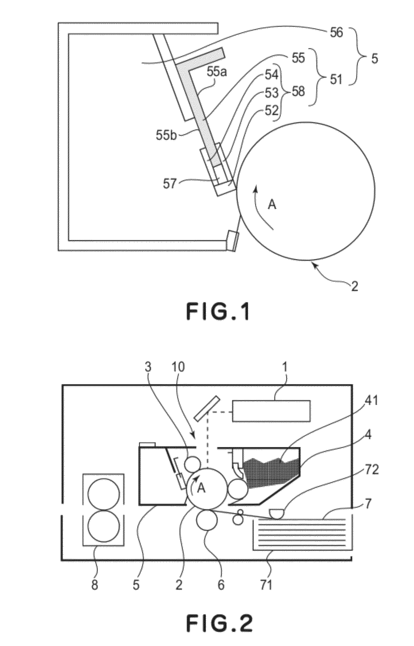
[0026]FIG. 2 is a schematic sectional view showing the image forming apparatus in this embodiment. An image forming operation of the image forming apparatus will be described.

[0027]Laser light modulated depending on an image signal is outputted in a scanning manner from a scanner unit 1 including a laser, a polygon mirror and a lens system, so that a surface of a photosensitive drum 2 as the image bearing member is irradiated with the laser light. The photosensitive drum 2 is uniformly charged by a primary charger 3 including a charging roller, so that an electrostatic latent image is formed on the surface of the photosensitive drum 2 by the irradiation with the laser light. The electrostatic latent image is developed with a toner 41 as the developer in a developing device 4, thus being visualized as a toner image (developer image). On the other hand, a recording material (toner (developer) image receiving member) 7 accommodated in a cassette 71 is fed and conveyed by a feeding roll...

embodiment 2

[0045]In this embodiment, different from Embodiment 1, the thickness of the first connecting portion 3 is changed. In the following description, a difference in constitution from Embodiment 1 will be described and the same constitution as Embodiment 1 will be omitted from the description.

[0046]FIGS. 6(a) to 6(c) are schematic views each showing the cleaning member 51 in this embodiment. In FIG. 6(a), the thickness of the first connecting portion is t1=0.4 mm and the thickness of the second connecting portion is t2=0.4 mm, i.e., t1=t2. In FIGS. 6(b) and 6(c), the thickness t1 is increased to 0.6 mm and 0.8 mm, respectively, while keeping the thickness t2 of 0.4 mm. In these figures, dimensions (unit: mm) of the respective portions are indicated similarly as in FIGS. 4(a) and 4(b).

[0047]FIG. 7 is a graph showing a result of measurement of a change in contact pressure with the entering amount of the cleaning members 51 shown in FIGS. 6(a), 6(b) and 6(c). FIG. 8 is a graph showing a res...


PUM


Abstract

A cleaning member, for use in an image forming apparatus in which a developer image formed on an image bearing member is to be transferred onto a developer image receiving member to form an image, for removing a developer remaining on the image bearing member after the transfer includes an elastic blade portion, having flexibility, for removing the developer remaining on the image bearing member in contact with the image bearing member in a bent state; and a supporting portion for supporting the elastic blade portion. The elastic blade portion includes, in a cross section perpendicular to a longitudinal direction of the elastic blade at a position in which the developer image is to be formed with respect to the longitudinal direction, a contact portion contacted to the image bearing member when the cleaning member is used in the image forming apparatus, a first connecting portion for connecting the contact portion and a portion of the supporting portion close to the image bearing member, and a second connecting portion for connecting the contact portion and a portion of the supporting portion remote from the image bearing member. The supporting portion, the contact portion, the first connecting portion and the second connecting portion define a hollow area.

Description

TECHNICAL FIELD[0001]The present invention relates to a flexible cleaning member for removing a developer on an image bearing member in contact with the image bearing member.BACKGROUND ART[0002]In an image forming apparatus such as a printer, a latent image is formed on a photosensitive drum, as the image bearing member which has been uniformly charged, by effecting selective light exposure and the latent image is visualized with toner as the developer to form a toner image, and then the toner image is transferred onto a recording material to effect image recording. After the toner image is transferred, a surface of the photosensitive drum is cleaned by the cleaning member and prepares for subsequent image formation. As a cleaning means for cleaning the photosensitive drum surface, a cleaning device for cleaning the photosensitive drum surface by bringing an elastic blade consisting of a rubber or the like as the cleaning member into contact with the photosensitive drum surface has ...

Claims


Application Information

Patent Timeline
Patent Type & Authority Applications(United States)
IPC IPC(8): G03G21/00
CPCG03G2221/0005G03G21/0011
Inventor SATO, HIROSHI
Owner CANON KK
Why Eureka
Try Eureka