System and method for tumor analysis and real-time biopsy guidance

a tumor location and biopsy guidance technology, applied in the field of imaging systems and methods, can solve the problems of reduced mammography sensitivity, reduced mammography density, and less than perfect screening methods

Inactive Publication Date: 2012-05-24
MAYO FOUND FOR MEDICAL EDUCATION & RES
View PDF3 Cites 19 Cited by
  • Summary
  • Abstract
  • Description
  • Claims
  • Application Information

AI Technical Summary

Problems solved by technology

Despite the success of screening mammography, however, it is also recognized that mammography is a less than perfect screening method.
The limitations of mammography are particularly evident when it is used on women having mammographically-dense breasts.
The reduction of sensitivity of mammography with the increase of mammographic density is compounded by the fact that increased breast density is a significant risk factor for breast cancer.
Given that a dense breast pattern is more characteristic of younger women, this factor significantly diminishes the value of mammography in the screening of young women who have a high familial or genetic risk of breast cancer.
A second major limitation to screening mammography lies in the evaluation of women at high risk of breast cancer.
Most of these studies have been performed with women with an average age of forty, so part of the explanation for the poor performance of mammography in these studies may be due to the presence of dense breast patterns in a significant percentage of the mammographic images.
However, while supplement

Method used


Image

  • System and method for tumor analysis and real-time biopsy guidance
  • System and method for tumor analysis and real-time biopsy guidance
  • System and method for tumor analysis and real-time biopsy guidance

Examples


embodiment 204

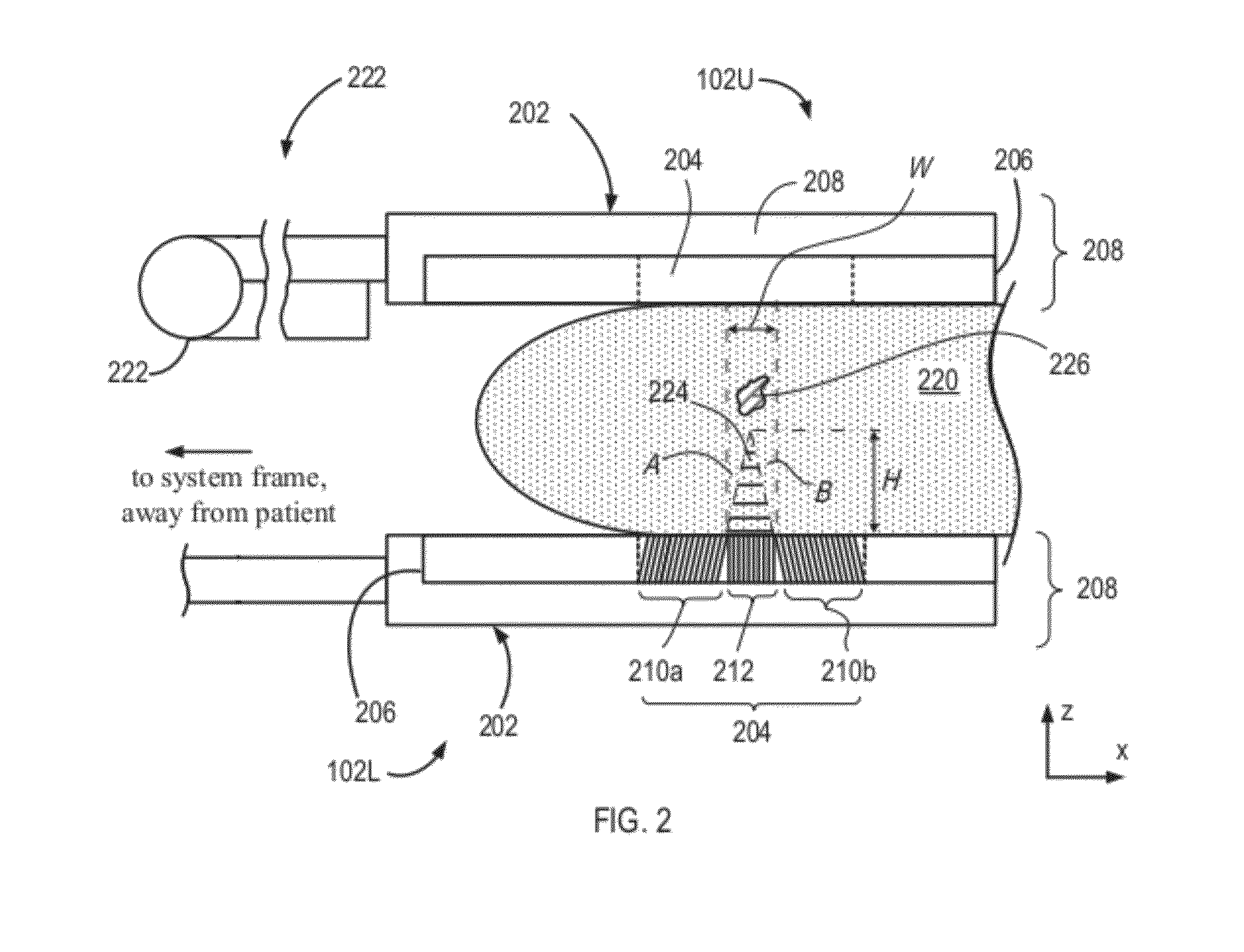
[0031]In comparison with a traditional collimator that contains a single collimating section, the holes or channels of which are directed substantially perpendicular to the plane of a supporting detector head (for example, to the plane of the head 102L or xy-plane), the embodiment 204 is characterized by an approximately two-fold increased sensitivity and, in addition, permits estimation of the depth of the lesion 226 within the breast tissue 220. As discussed further below, the assessment of lesion depth in the breast 220 is effectuated by considering the relative distances to the lesion as reflected by portions of the image that are respectively associated with the collimating sections 210a, 210b, and 212 of the collimator 204.

[0032]Specifically, and in further reference to FIG. 2, the three-sectional structure of the collimator 204 defines a “dead” or “dark” zone denoted in a cross-sectional view of FIG. 2 as a triangular area 224. The terms “dead” or “dark” refer to the fact tha...

embodiment 300

[0039]In clinical use, the embodiment of the conical slant-hole collimator would be positioned directly underneath the lesion to be biopsied. FIG. 5 shows a portion 500 of the collimator repositioning system containing the embodiment 300 on a tray 504 that is configured to be slidable into a collimator sleeve 508. Lead plates 510 adjacent the collimator 300 on the tray 504 are positioned to limit the field-of-view of the detector (not shown) under the collimator 300 to that corresponding only to an area of the collimator 300. In use, the tray 504 is caused to slide into the sleeve 508 and is positioned beneath the lesion. For lesions located close to the chest wall (within approximately half the diameter of the conical collimator from the chest wall), a semi-circular version of the collimator (containing a left half of the collimator 300 as presented in FIG. 3) would be utilized to gain access to this part of the breast. While possessing only half the sensitivity of the full conical...

embodiment 100

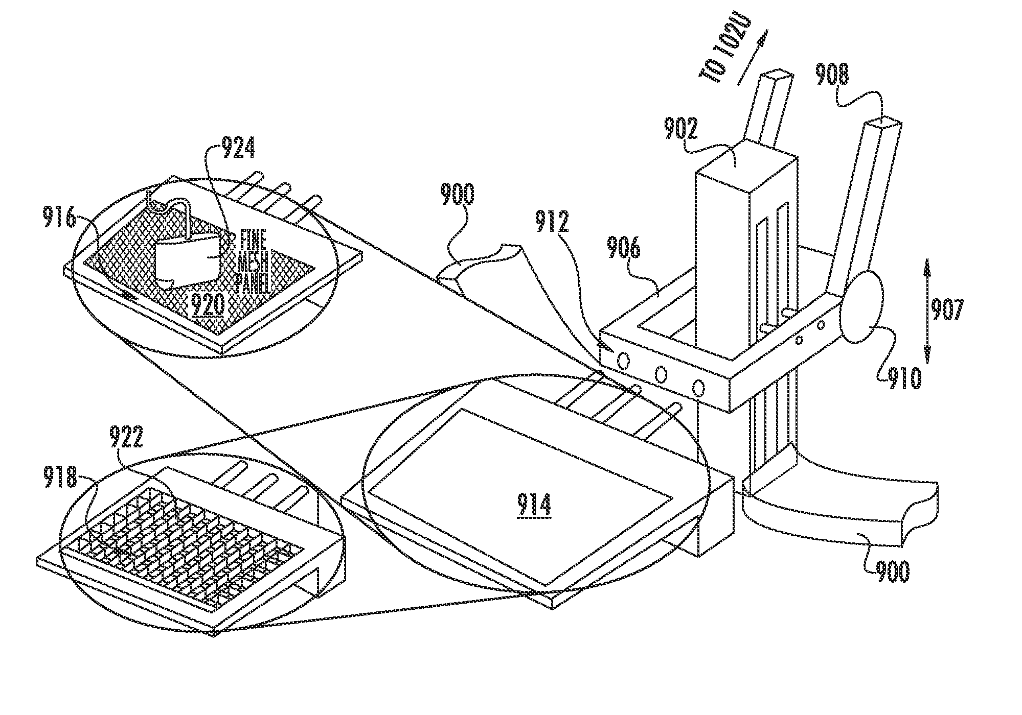
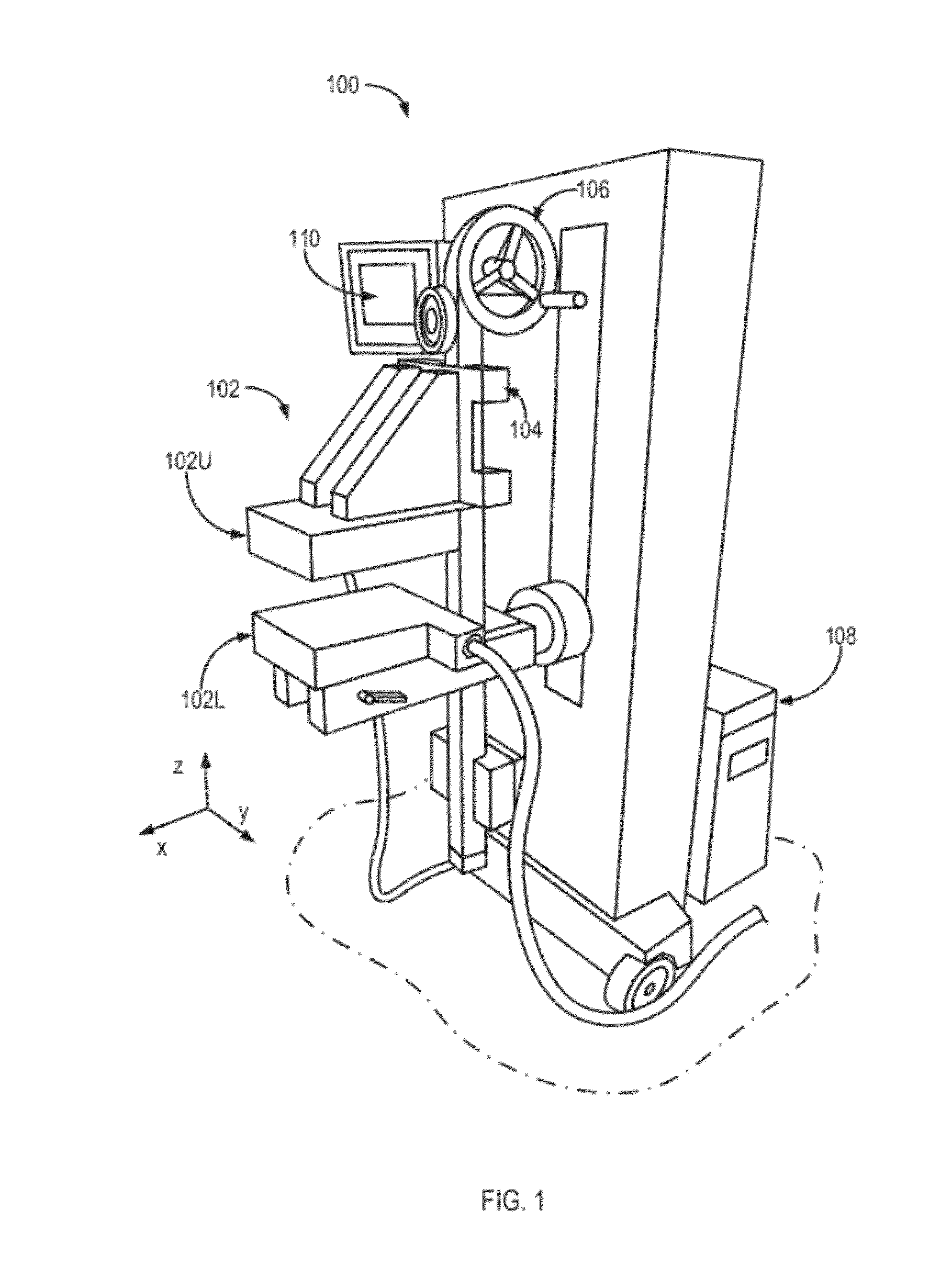
[0048]Referring again to FIGS. 1, 2 and 4B, imaging of the breast 220 is performed using the aforementioned MBI system embodiment 100 of FIG. 1 that includes, in relevant part, a set-up of FIG. 4A. The results of such imaging which permit a calculation of an in-plane (x and y) location of a lesion in the breast 220 as well as its depth (relative position along the z-axis), and relative uptake of an administered radionuclide. In one embodiment, As illustrated in FIG. 4B and further described below in reference to FIGS. 8 and 9, the upper detector head 102U may be affixed to a rotatable gantry arm, which provides a rotation of the upper detector head 102U (for example, in the xz-plane, about a hinge 222) and facilitates interchangeability of the upper detector head 102U with other functional components devices, such as an ultrasound system, for example.

[0049]In particular, FIG. 8 shows a reconfigurable embodiment 800 of the invention configured to facilitate imaging of breast tissue w...


PUM


Abstract

A system and method for molecular breast imaging (MBI) provides enhanced tumor analysis and, optionally, a real-time biopsy guidance. The system includes a detector head including a gamma ray detector and a collimator. The collimator include multiple collimation sections having respectively different spatially-oriented structures. In addition or alternatively, the multiple collimating section have respectively different collimation characteristics. An image of the tissue acquired with the system may include spatially separate image portions containing image information about the same portion of the imaged tissue. A system is optionally configured to acquire updatable images to provide real-time feedback about the biopsy procedure.

Description

CROSS-REFERENCE TO RELATED APPLICATIONS[0001]The present application claims benefit of and priority from a U.S. Provisional Patent Application No. 61 / 417,139 titled “System and Method for Tumor Analysis and Real-Time Biopsy Guidance” and filed on Nov. 24, 2010. The entire disclosure of the above-mentioned provisional application is incorporated herein by reference.TECHNICAL FIELD[0002]The present invention relates to systems and methods for imaging and, more particularly, to systems and methods for tumor location analysis and real-time biopsy guidance using molecular breast imaging.BACKGROUND OF THE INVENTION[0003]Breast cancer screening has been recommended for many decades, particularly in women over the age of fifty. The combination of early detection and improved therapy of breast cancer in the U.S. has resulted in a significant reduction in breast cancer mortality, with similar reductions being observed in other countries. Despite the success of screening mammography, however, ...

Claims


Application Information

Patent Timeline
IPC IPC(8): A61B6/00A61B10/02G01T1/161A61B8/00
CPCA61B6/0414A61B6/06A61B6/12A61B6/4258A61B6/4291A61B6/48A61B10/0233A61B8/403A61B8/4209A61B8/485A61B8/5261A61B10/0041A61B6/502
Inventor O'CONNOR, MICHAEL K.HRUSKA, CARRIE B.WEINMANN, AMANDA L.
Owner MAYO FOUND FOR MEDICAL EDUCATION & RES
Why Eureka
Try Eureka