
Intramedullary nail, system, and method with dynamic compression

a technology of dynamic compression and intramedullary nail, applied in the field of intramedullary nail with dynamic compression, can solve the problems of fracture fragments not maintaining compression across fracture fragments, skeletal function loss, and scar tissue that is not mineralized,

Active Publication Date: 2012-05-24
AFCN
View PDF4 Cites 54 Cited by
  • Summary
  • Abstract
  • Description
  • Claims
  • Application Information

AI Technical Summary

Benefits of technology

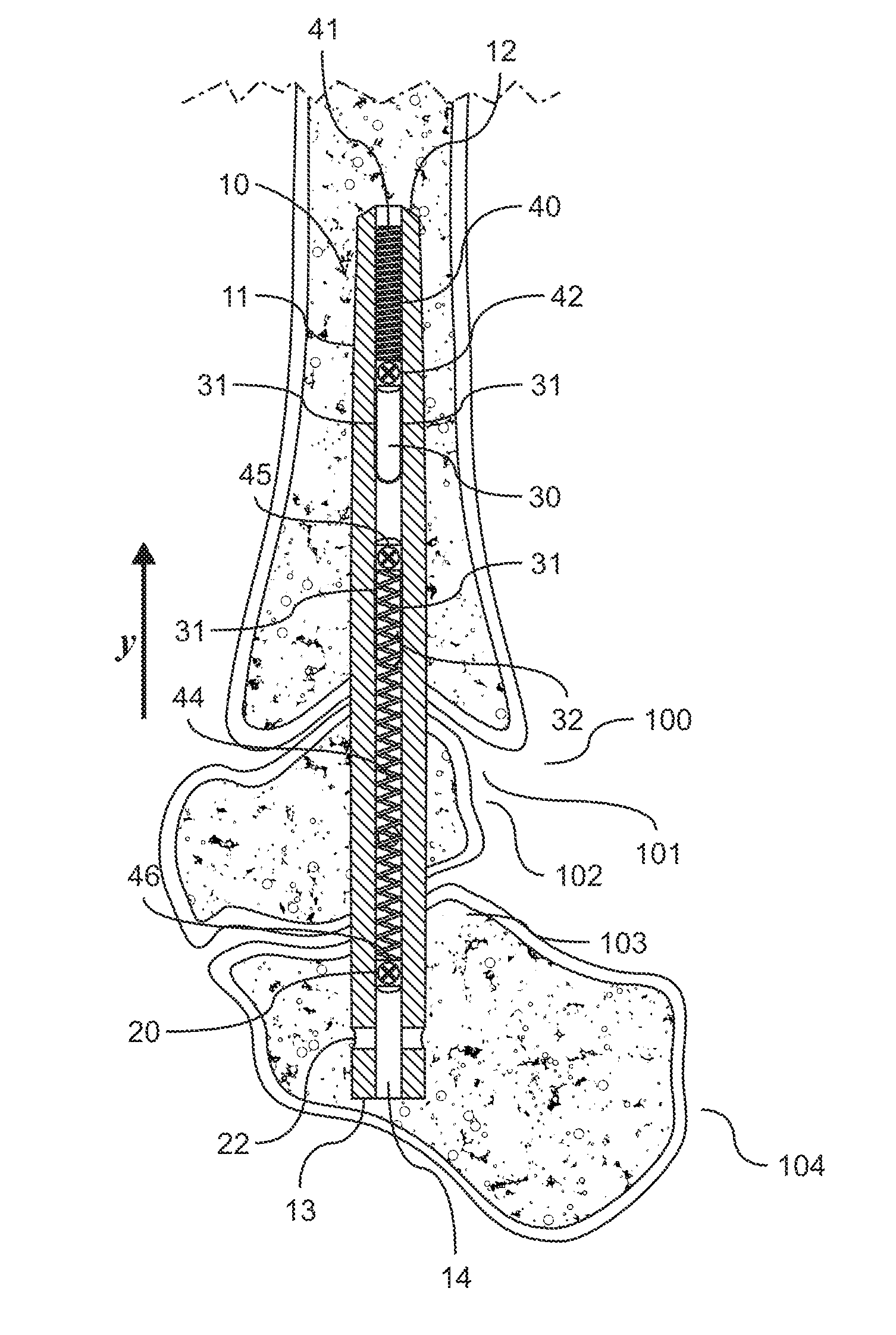
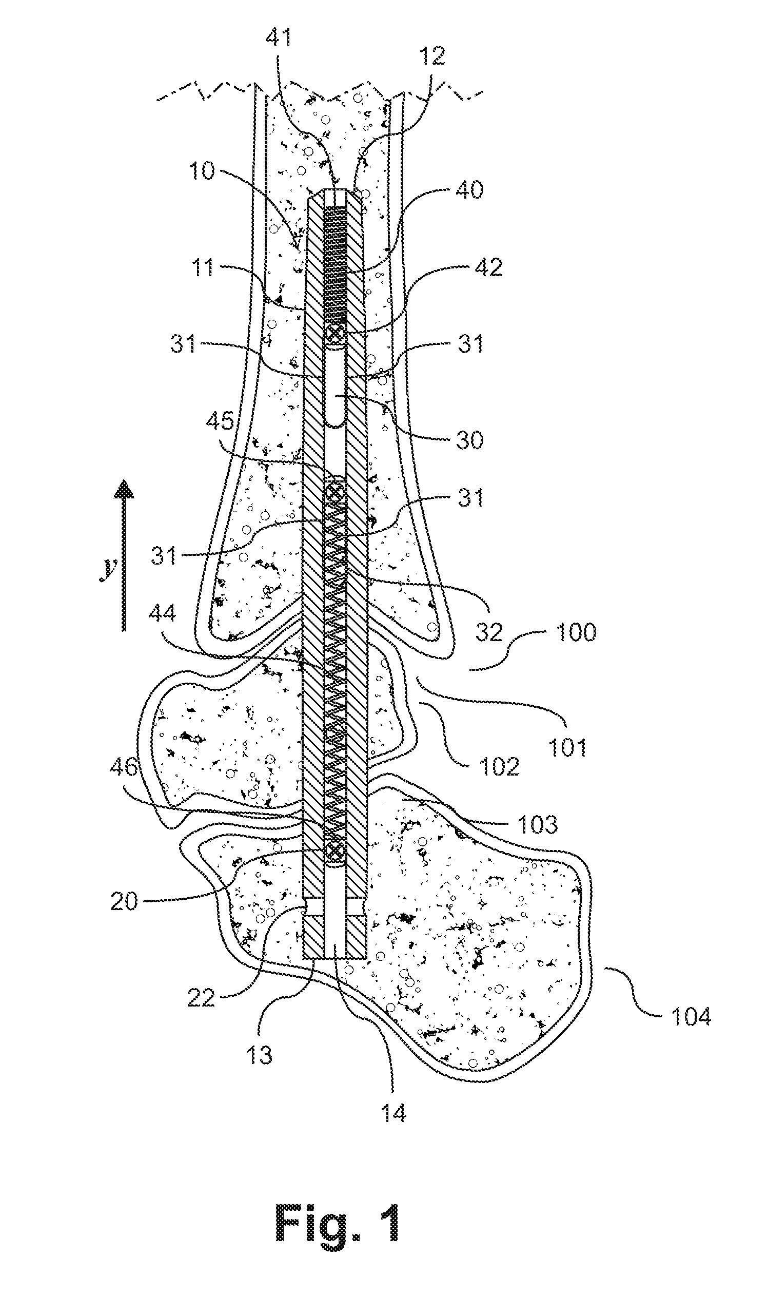
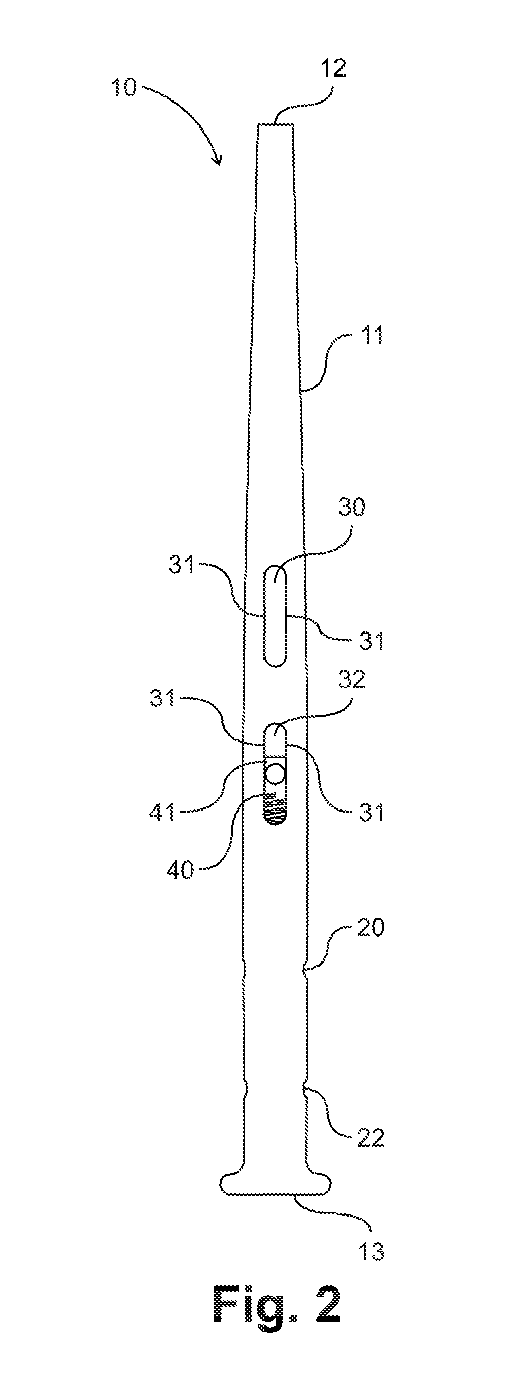
[0020]In another embodiment, the nail further comprises a projection, wherein the projection is located within the inner channel between a first elongated aperture and a second elongated aperture. The first end of a first compression member abuts the proximal end of the nail and the second end of the first compression member is capable of engaging a fastener received in the first elongated aperture. The first end of a second compression member abuts the projection and the second end of the second compression member is capable of engaging a fastener received in the second elongated aperture. Both of the first and second compression member can exert a force to move the nail and thereby provide compression to a fusion or fracture site located between the first distal aperture and the second elongated aperture when the fasteners are received in the nail. The first compression member can be a compression spring, a torsional spring, a Belleville washer, or a plurality of Belleville washers, and the second compression member is can be a compression spring, a torsional spring, a Belleville washer, or a plurality of Belleville washers.
[0025]Each of the foregoing embodiments can also comprise an appropriate number of fasteners to anchor the nail to the bone and engage with the one or more compression members. All of the foregoing embodiments can also have at least one distal aperture capable of permitting a fastener to pass through it at an oblique angle and be secured in a position transversing the nail. A compression member can also be capable of engaging the fastener received at an oblique angle in the distal aperture. In addition, the elongated and distal apertures of the nail can have axes transversing the nail that are parallel or perpendicular with one another. The elongated body of all embodiments of the nail can have a cross-sectional shape that provides rotational stability to the nail. For example, the cross-sectional shape can be an oval, triangle, cruciate shape, partially oval, clover shape, star shape, trapezoidal, rhomboid, or any other irregular geometric shape.

Problems solved by technology

However, problems can arise when the bone fracture or fusion site is not sufficiently stabilized during the healing timeframe.
The unmineralized scar tissue is not load-supporting and skeletal function is lost.
However, over time, the stainless steel and titanium fixation constructs (screws, plates and nails) do not maintain compression across the fracture fragments.
As the necrotic surfaces of the fracture are resorbed, a non-load bearing gap develops between the fragments, thereby decreasing compression and increasing the risk of interfragmentary motion and scar tissue formation.
Loss of compression is contrary to the objectives of fracture or fusion fixation in general, and osteosynthetic implants in particular.
However, many intramedullary nail systems include devices, both internal and external to the nail itself, which provide compression only at the time of insertion.
The problem remains that during the healing process, re-absorption results in a gap across the healing site, and compression is lost.
But, the current nails are designed to allow this compression only after weight bearing has begun, employing the very ground reactive forces encountered during weight bearing itself to provide the necessary compression.
Unfortunately, resorption occurs much earlier during the healing process than does weight bearing, especially in the many cases in which additional procedures such as mid-foot fusion, are performed simultaneously with rear-foot to ankle fusion.
Where the current art contains compression, it does not allow selection of compressive force and it couples compression with positioning of the nail, which can be detrimental to achieving proper positioning with the correct compression force desired.
Unfortunately, multiple limitations are inherent in this design.
First, the amount of compression is extremely variable and may be minimal, due to the fact that the spring is only loaded proportionate to the amount that the female end of the screw is extended.
Secondly, the fact that the screw length changes during screw insertion is problematic because with a fixed amount of bone available for screw insertion, the screw must be a precise and predictable length to ensure appropriate placement in the anatomy.
If the female member of the screw encounters hard bone during insertion, the leading male member will prematurely extend, thereby altering the length of the screw.
This is problematic in that hydraulic fluid mechanisms are excessively complicated and not desirable for implantation.
External mechanisms to provide compression of an intramedullary nail must violate the skin barrier and traverse to the bone, thereby presenting the likely possibility of superficial or deep infection.
Nitinol or memory metal nails have been described, but memory metal is also complicated in many cases, requiring the device to be delivered to the OR frozen, or heated with special machinery during implantation in order to activate the compression mechanism.
Also, in order for a memory metal nail to compress, it would require that it also expand in thickness or diameter, which is not desirable in this application.
This is disadvantageous in that, as noted above, the amount of compression is extremely variable and may be minimal due to the fact that the compression is dependent on the amount of available space in the bone for screw insertion.
A screw having a varying length that changes during screw insertion is also problematic because the screw should have a precise and predictable length to ensure appropriate placement in the anatomy, considering the fixed amount of bone available for screw insertion.
The devices are also disadvantageous in that the screws only utilize extension springs to provide compression and cannot use different or multiple compression means simultaneously to achieve dynamic compression.
In addition to lack of continuous dynamic compression, a provision for rotational stability at the level of the fusion site is lacking with Intramedullary Nail systems currently described in the art.
While translation and bending forces are controlled well with the current intramedullary nail systems, it is well known that rotation may occur, which may negatively impact bone healing.

Method used


Image

  • Intramedullary nail, system, and method with dynamic compression
  • Intramedullary nail, system, and method with dynamic compression
  • Intramedullary nail, system, and method with dynamic compression

Examples


Embodiment Construction

[0049]The present invention overcomes disadvantages of the prior art, as identified and disclosed by the inventor, by providing a cannulated intramedullary nail and steps for its insertion so that continuous dynamic compression is applied across a fusion or fracture site. Continuous dynamic compression is accomplished through the employment of one or more mechanical compression members, such as compression or extension springs or biocompatible elastic or rubber bands, which are loaded into the cannulated canal of the nail itself. The compression mechanism is engaged with transfixion interlocking fasteners such as pins, rods, or screws that are inserted across the nail.

[0050]The detailed description set forth below in connection with the appended drawings is intended to provide example embodiments of the present invention and is not intended to represent the only forms in which the invention may be constructed or utilized. The description sets forth the functions and the sequences of...


PUM


Abstract

The present invention describes an intramedullary nail for use in orthopedic surgery for the fixation of bone fractures and fusion sites. The nail employs one or more internal loaded springs, biocompatible elastic or rubber bands, or other mechanism that provides continuous dynamic compression across the healing site throughout the healing process. By altering the size, tension and / or number of the internal compression devices, the amount of compression may be customized on a case-by-case basis. Further, the slots within the nail for its attachment can be utilized to create a torsional force when desired. The nail can have a cross-sectional shape that prevents its rotation. A system and method of use is also described.

Description

CROSS-REFERENCE TO RELATED APPLICATIONS[0001]The present application claims the benefit of priority from U.S. Provisional Application Ser. No. 61 / 416,934, filed on Nov. 24, 2010, the contents of which are hereby incorporated in this disclosure by reference in their entirety.BACKGROUND OF THE INVENTION[0002](1) Field of the Invention[0003]The present invention relates to an intramedullary nail with dynamic compression, and a system and method of use thereof[0004](2) Description of the Related Art[0005]To heal an injured bone properly, the bone must remain in stable position with the edges of the bone compressed against one another without motion. Intramedullary nails have been employed in orthopedic surgery for centuries to serve this purpose, as they are an excellent source of lasting axial and torsional stability, stiffness and rigidity. Intramedullary nailing has a long and interesting history that dates back to the 16th century. Küntscher developed modern intramedullary nailing t...

Claims


Application Information

Patent Timeline
Patent Type & Authority Applications(United States)
IPC IPC(8): A61B17/58
CPCA61B17/7241A61B17/7225
Inventor KINMON, KYLE
Owner AFCN
Learn More