Parallel cycle heat engines

a heat engine and parallel cycle technology, applied in the direction of machines/engines, mechanical equipment, lighting and heating apparatus, etc., can solve the problems of high temperature requirements, inability to capture and recycle heat, and high equipment cost, and achieve the effect of reducing operating labor and equipment cos

Active Publication Date: 2012-05-31
ECHOGEN POWER SYST
View PDF24 Cites 67 Cited by
  • Summary
  • Abstract
  • Description
  • Claims
  • Application Information

AI Technical Summary

Problems solved by technology

Other times it is not feasible to capture and recycle this heat because it is either too low in temperature or there is no readily available means to use as heat directly.
However, at least one of the key short-comings of a steam-based Rankine cycle is its high temperature requirement, which is not always practical since it generally requires a relatively high temperature (600° F. or higher, for example) waste heat stream or a very large overall heat content.
Also, the complexity of boiling water at multiple pressures/temperatures to capture heat at multiple temperature levels as the heat source stream is cooled is costly in both equipment cost and operating labor.
Furthermore, the steam-based Rankine cycle is not a realistic option for streams of small flow rate and/or low temperature.
However, the boiling heat transfer restrictions remain, and new issues such as thermal instability, toxicity or flammabi...

Method used


Image

  • Parallel cycle heat engines
  • Parallel cycle heat engines
  • Parallel cycle heat engines

Examples


Embodiment Construction

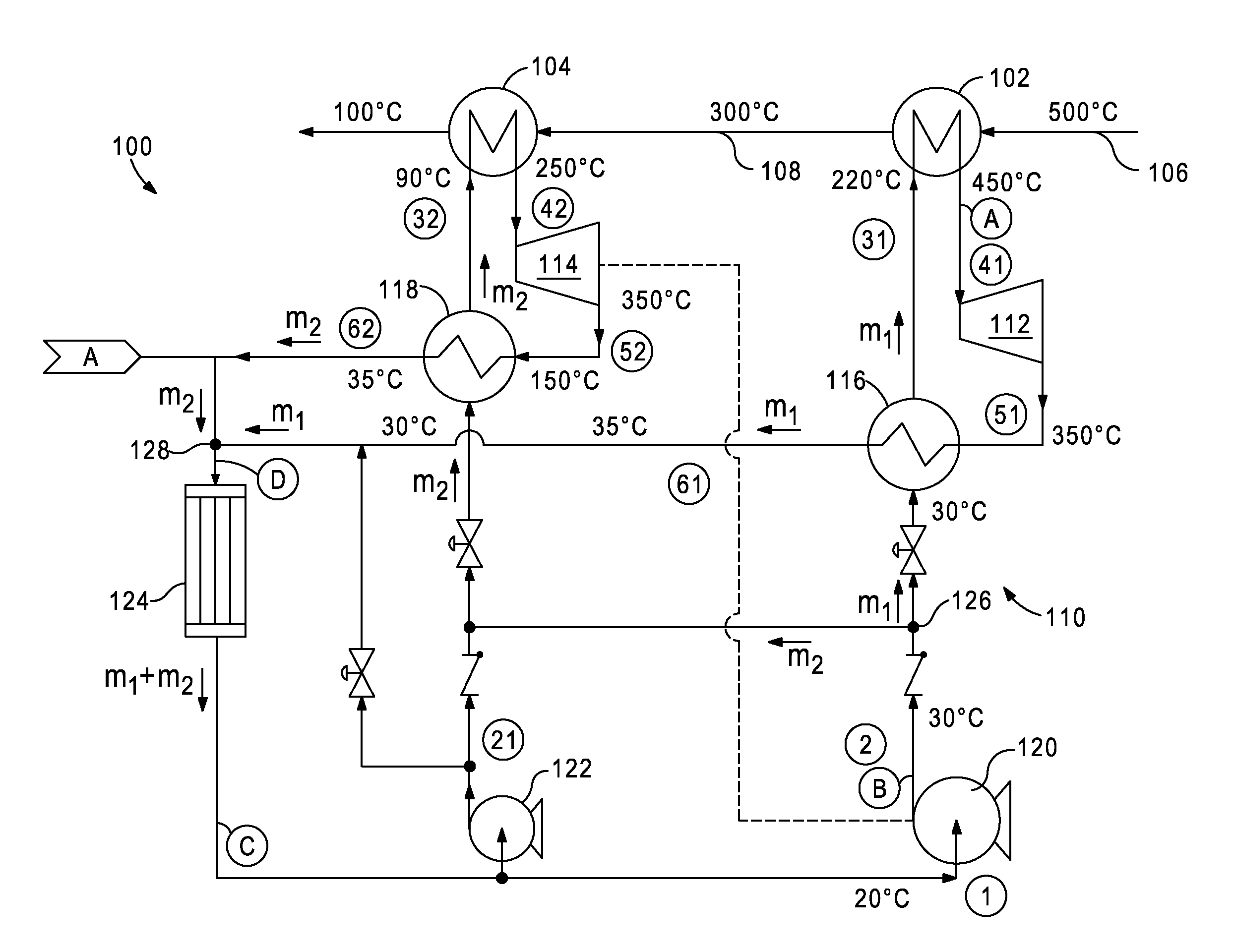
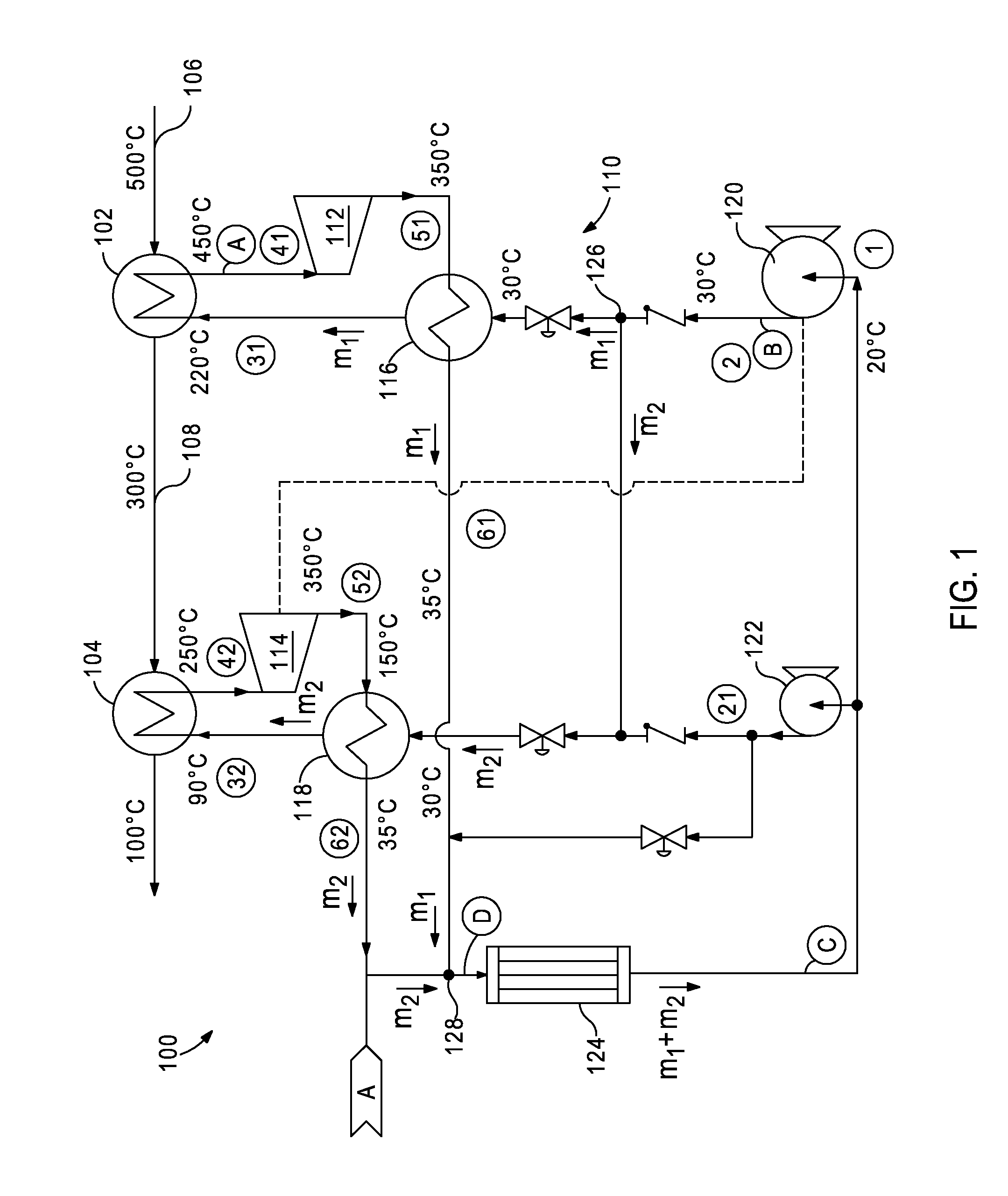
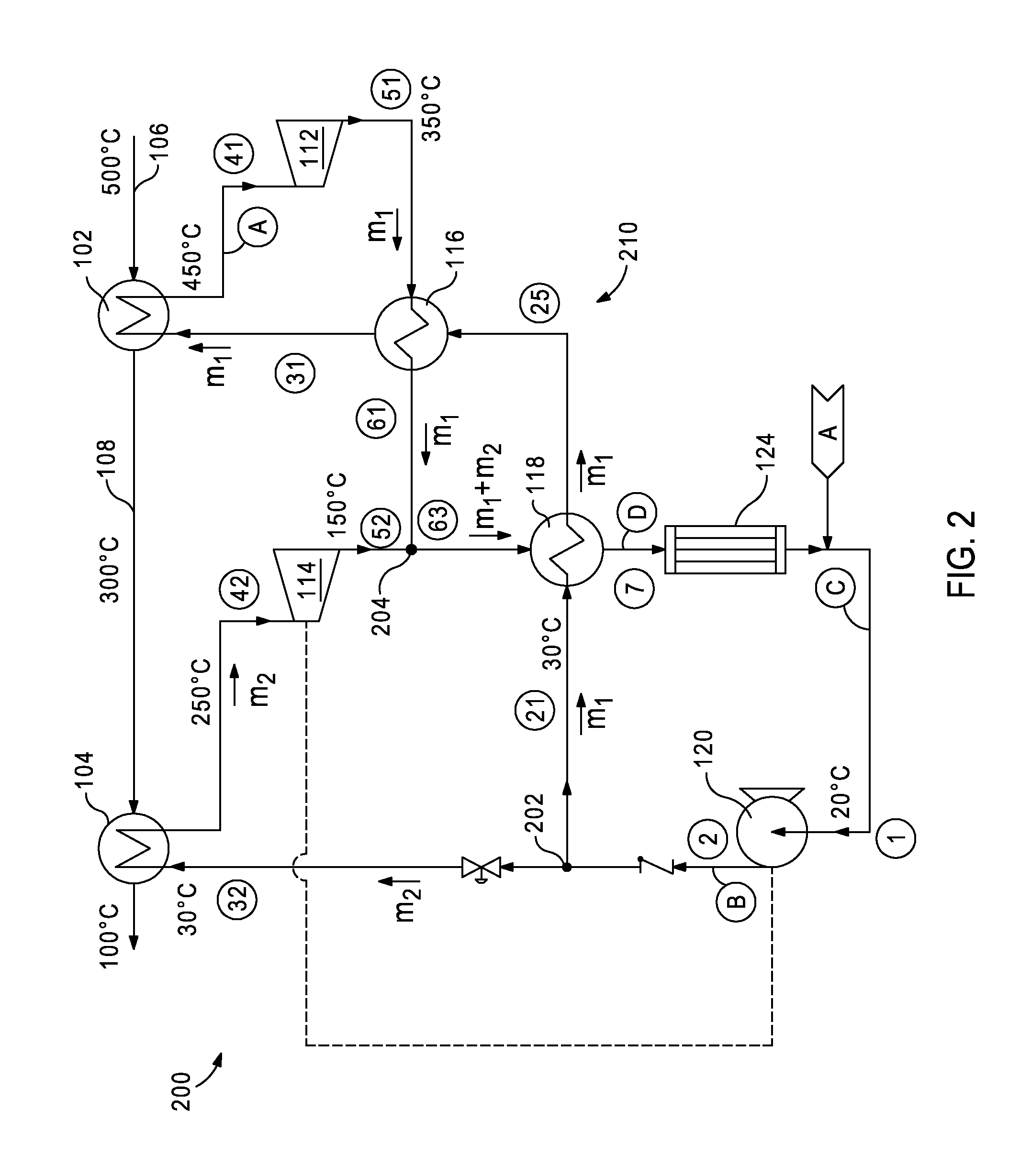
[0020]It is to be understood that the following disclosure describes several exemplary embodiments for implementing different features, structures, or functions of the invention. Exemplary embodiments of components, arrangements, and configurations are described below to simplify the present disclosure; however, these exemplary embodiments are provided merely as examples and are not intended to limit the scope of the invention. Additionally, the present disclosure may repeat reference numerals and / or letters in the various exemplary embodiments and across the Figures provided herein. This repetition is for the purpose of simplicity and clarity and does not in itself dictate a relationship between the various exemplary embodiments and / or configurations discussed in the various Figures. Moreover, the formation of a first feature over or on a second feature in the description that follows may include embodiments in which the first and second features are formed in direct contact, and m...


PUM


Abstract

Waste heat energy conversion cycles, systems and devices use multiple waste heat exchangers arranged in series in a waste heat stream, and multiple thermodynamic cycles run in parallel with the waste heat exchangers in order to maximize thermal energy extraction from the waste heat stream by a working fluid. The parallel cycles operate in different temperature ranges with a lower temperature work output used to drive a working fluid pump. A working fluid mass management system is integrated into or connected to the cycles.

Description

CROSS-REFERENCE TO RELATED APPLICATIONS[0001]This application claims priority to U.S. Provisional Patent Application Ser. No. 61 / 417,789, filed Nov. 29, 2010, the contents of which are hereby incorporated by reference in their entirety into the present application.BACKGROUND[0002]Heat is often created as a byproduct of industrial processes where flowing streams of liquids, solids, or gasses that contain heat must be exhausted into the environment or otherwise removed from the process in an effort to maintain the operating temperatures of the industrial process equipment. Sometimes the industrial process can use heat exchanging devices to capture the heat and recycle it back into the process via other process streams. Other times it is not feasible to capture and recycle this heat because it is either too low in temperature or there is no readily available means to use as heat directly. This type of heat is generally referred to as “waste” heat, and is typically discharged directly i...

Claims


Application Information

Patent Timeline
IPC IPC(8): F01K27/02F01K25/00F01K25/08
CPCF01K13/02F01K25/10F01K25/103F01K23/04F22B35/086F01K23/10F01K25/02F01K7/16
Inventor HELD, TIMOTHY JAMESVERMEERSCH, MICHAEL LOUISXIE, TAOMILLER, JASON
Owner ECHOGEN POWER SYST
Why Eureka
Try Eureka