Solar cell and method for fabricating the same
Inactive Publication Date: 2012-05-31
IND TECH RES INST
View PDF2 Cites 15 Cited by
- Summary
- Abstract
- Description
- Claims
- Application Information
AI Technical Summary
Benefits of technology
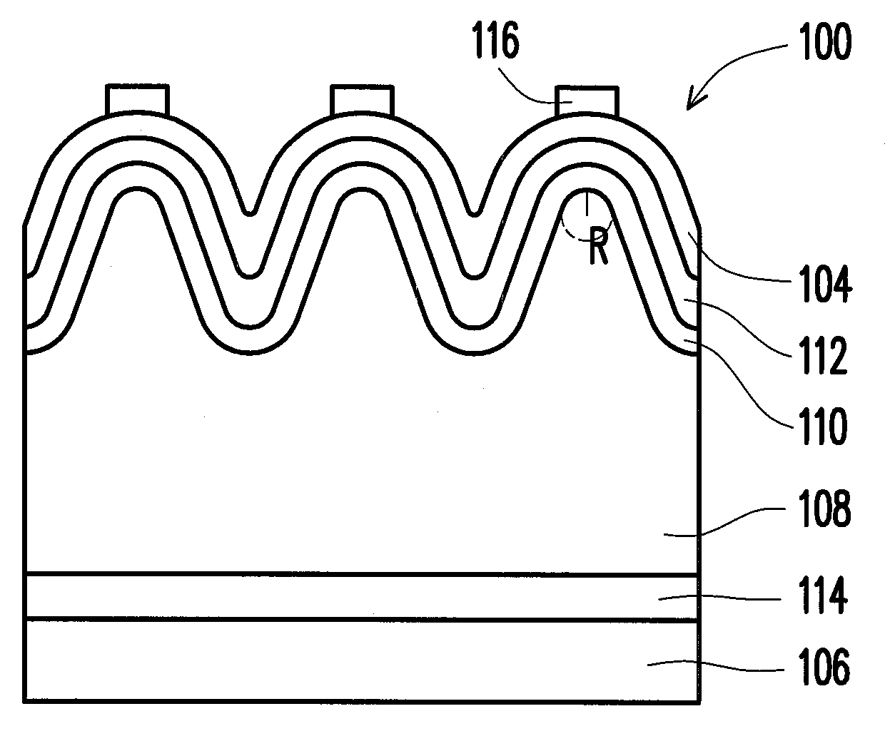
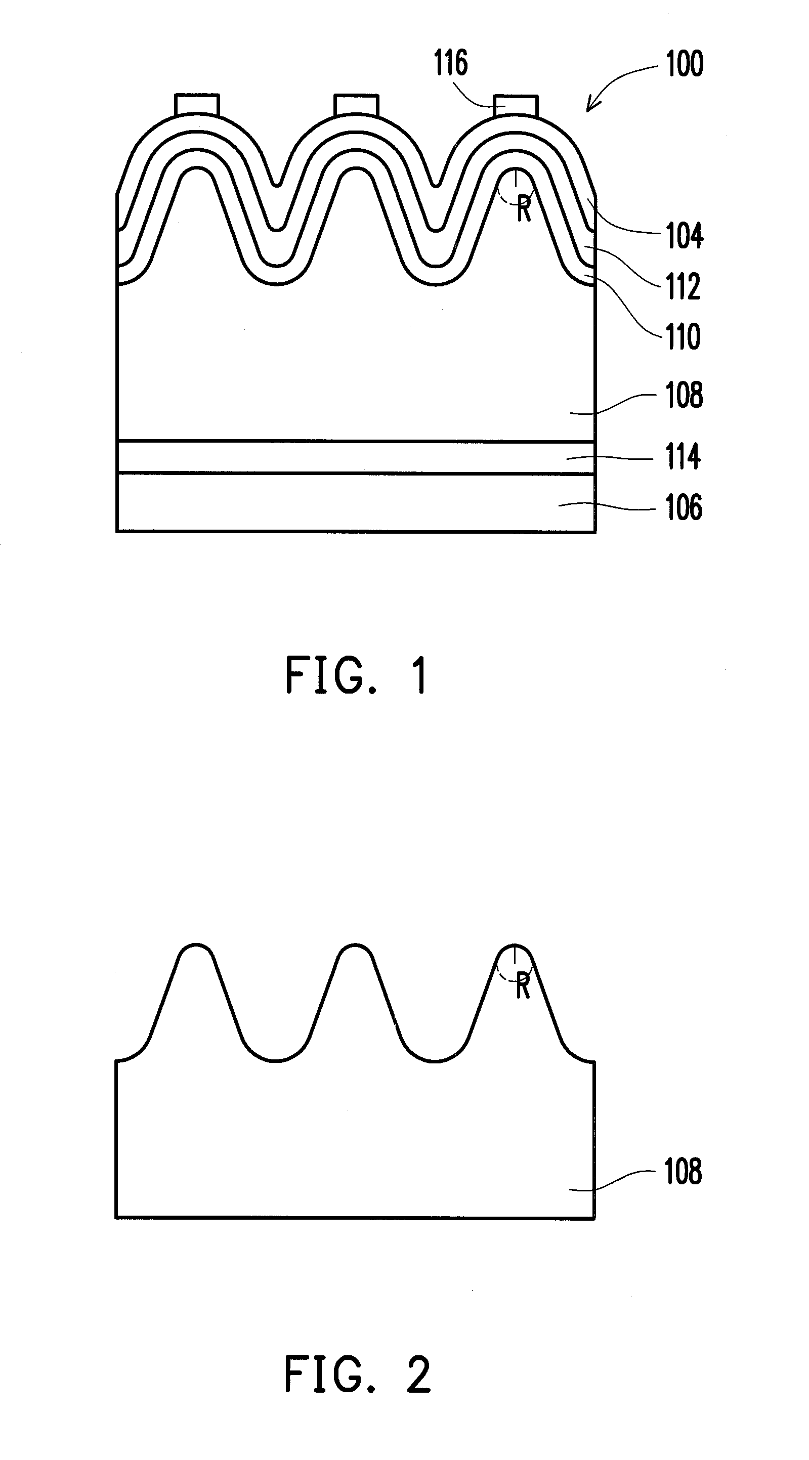
[0009]In light of the above, the disclosure provides a solar cell and a method for fabricating the same. By using laser ablation to modify a surface structure of a silicon substrate, uniformity of deposited films is increased, and device conversion efficiency is enhanced.
[0013]Moreover, since the laser treatment is used to form the above pyramid structure, by controlling the focusing position, energy, and irradiation time of the laser, the structures at different positions such as the top portion or the bottom portion of the pyramid structure are altered, thereby simplifying the process of controlling the contour of the pyramid structure without losing light trapping abilities. Therefore, the method for fabricating the solar cell according to the disclosure is simple and adjustable.
Problems solved by technology
However, if an angle of the pyramid structures is too small and a crest line is too sharp, subsequent film formation process are easily affected, so that films that are formed are likely to have problems of non-uniform thickness and may even become broken through, thereby causing short circuits.
Method used
View moreImage
Smart ImageViewing Examples
Examples
examples 1 to 3
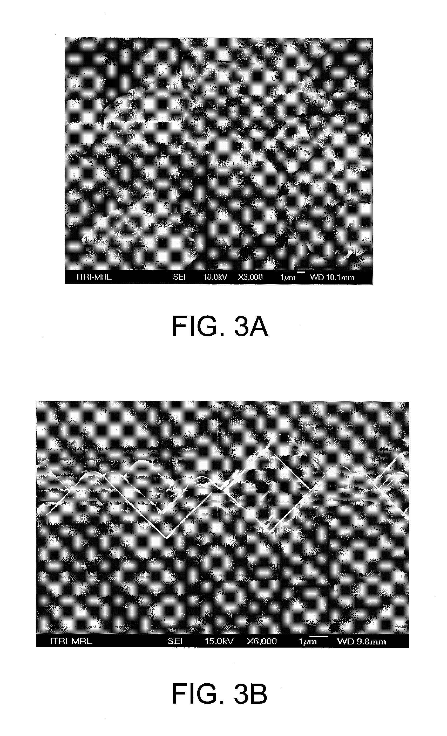
[0059]After forming the pyramid structure on the silicon substrate, the laser treatment is performed on the silicon substrate. The parameters for the laser treatment are as follows.
The wave length of the laser: 532 nm
The focusing height: −14.6 mm
The size of the light beam: 50 nm
The energy intensity: 2 J / m2 (example 1), 2.25 J / m2 (example 2), 2.5 J / m2 (example 3)
The speed of the carrying platform: 100 mm / sec
Login to View More PUM
 Abstract
A solar cell and a method for fabricating the same are described. A pyramid structure is formed on a silicon substrate. A laser treatment is performed on the pyramid structure, so that a top portion of the pyramid structure has an arc shape, and a round is formed at a crest line of the pyramid structure. Films formed during subsequent processes hence have a uniform thickness and conversion efficiency of the solar cell is improved.
Description
CROSS-REFERENCE TO RELATED APPLICATION[0001]This application claims the priority benefit of Taiwan application serial no. 99141512, filed on Nov. 30, 2010. The entirety of the above-mentioned patent application is hereby incorporated by reference herein and made a part of this specification.BACKGROUND OF THE INVENTION[0002]1. Field of the Invention[0003]The disclosure is related to a photoelectric device, and in particular to a solar cell which enhances photoelectric conversion efficiency and a method for fabricating the same.[0004]2. Description of Related Art[0005]Solar energy is a type of inexhaustible and non-pollutive energy and is receiving the most attention when it comes to solving the pollution and shortage faced by fossil fuels. Solar cells are able to directly convert solar energy into electricity and are hence currently an important research topic.[0006]Silicon-based solar cells are a common type of solar cells in the industry. The principle of silicon-based solar cells ...
Claims
Login to View More Application Information
Patent Timeline
 IPC IPC(8): H01L31/072H01L31/02
CPCH01L31/03529H01L31/0684Y02E10/547H01L31/1804H01L31/0747Y02P70/50
Inventor CHEN, CHIEN-HSUNCHEN, YU-RU
Owner IND TECH RES INST
Features
- R&D
- Intellectual Property
- Life Sciences
- Materials
- Tech Scout
- Unparalleled Data Quality
- Higher Quality Content
- 60% Fewer Hallucinations
Learn More Browse by: Latest US Patents, China's latest patents, Technical Efficacy Thesaurus, Application Domain, Technology Topic, Popular Technical Reports.
© 2025 PatSnap. All rights reserved.Legal|Privacy policy|Modern Slavery Act Transparency Statement|Sitemap|About US| Contact US: help@patsnap.com


