Point-of-use water treatment system

a technology of water treatment system and point-of-use, which is applied in water treatment multi-stage treatment, water/sewage multi-stage treatment, separation process, etc. it can solve the problems of user inability to configure or adapt the unit to meet a particular need, the device mounted in an under-the-counter application may be difficult to access for maintenance purposes, and the wts unit used in a countertop application may not have the most desired appearan

Inactive Publication Date: 2012-05-31
ACCESS BUSINESS GRP INT LLC
View PDF5 Cites 48 Cited by
  • Summary
  • Abstract
  • Description
  • Claims
  • Application Information

AI Technical Summary

Benefits of technology

[0007]In one embodiment, the water treatment system is adapted particularly for difficult-to-reach installation locations by providing a vessel containing the treatment assembly that can be easily removed from a base and moved to a different location, for instance, for changing the filters. The base may include a first flow path and a second flow path for directing water into and out of the vessel. When the vessel is positioned on the base, the an inlet on the vessel is in fluid communication with the first flow path and an outlet on the vessel is in fluid communication with the second flow path. Portions of the base may be movable to accommodate for the removal of the vessel from the base.
[0008]In another embodiment, the water treatment system provides an aesthetically pleasing exterior arrangement for installation in a more visible setting. The water treatment system again includes a vessel containing a treatment assembly, such as a water filtration media or a water disinfecting assembly. A plate is connected to the vessel, and the plate includes at least one electrical connection. At least one electronics brick is removably attached to the plate such that the electronics brick is in electrical communication with the plate. The electronics brick includes electronic circuitry and may include sensors for communicating with the filters or disinfecting assembly, a visual display, and other features. In one embodiment, the plate includes a series of attachment members spaced along the plate for snap-fitting to various sizes of electronic bricks. A plurality of electronic bricks may be arranged on the plate to meet the user's desired application.
[0009]In another embodiment, the water treatment system incorporates one or more stackable and interchangeable filter blocks, which enables a user to configure the treatment system for removal of a specific type of contaminant that may be particularly prevalent in the water. In this embodiment, a baffle may be positioned within the vessel. The filter blocks are stacked within the vessel, with each filter block including a filter media, a top end cap on a top surface of the filter media and a bottom end cap on a bottom surface of the filter media. The top and bottom end caps are arranged to create a flow path through each of the filter medias. For instance, the top end caps may seal against the baffle and the bottom end cap may seal against the sidewall of the vessel to direct water flowing into the vessel across the top end cap of each filter block and through each filter media.

Problems solved by technology

Although current models of water treatment systems have become effective at removing and treating contaminates, they suffer from a common drawback in that most models are “one size fits all” with respect to filtration, disinfection and design.
They work well for many water types and uses, but users are unable to configure or adapt them to meet a particular need.
As a result, a WTS unit used in a countertop application may not have the most desired appearance, such as a large graphic heavy display, and a device mounted in an under-the-counter application may be difficult to access for maintenance purposes.

Method used


Image

  • Point-of-use water treatment system
  • Point-of-use water treatment system
  • Point-of-use water treatment system

Examples


first embodiment

I. First Embodiment

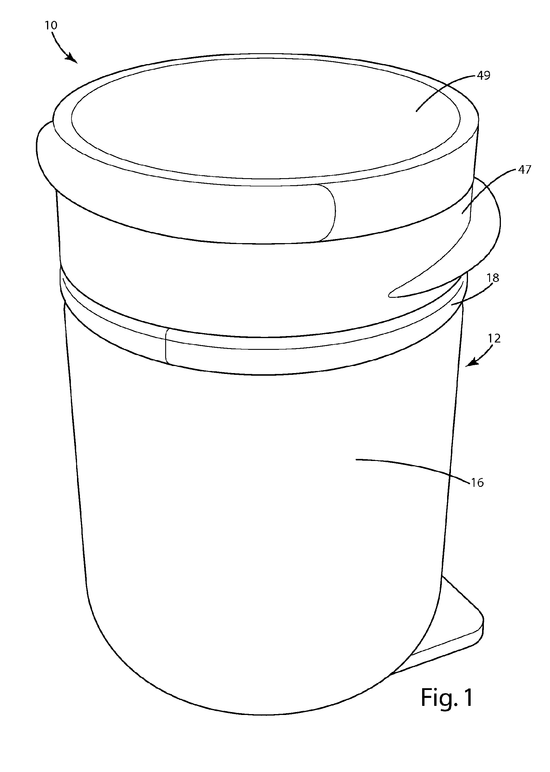
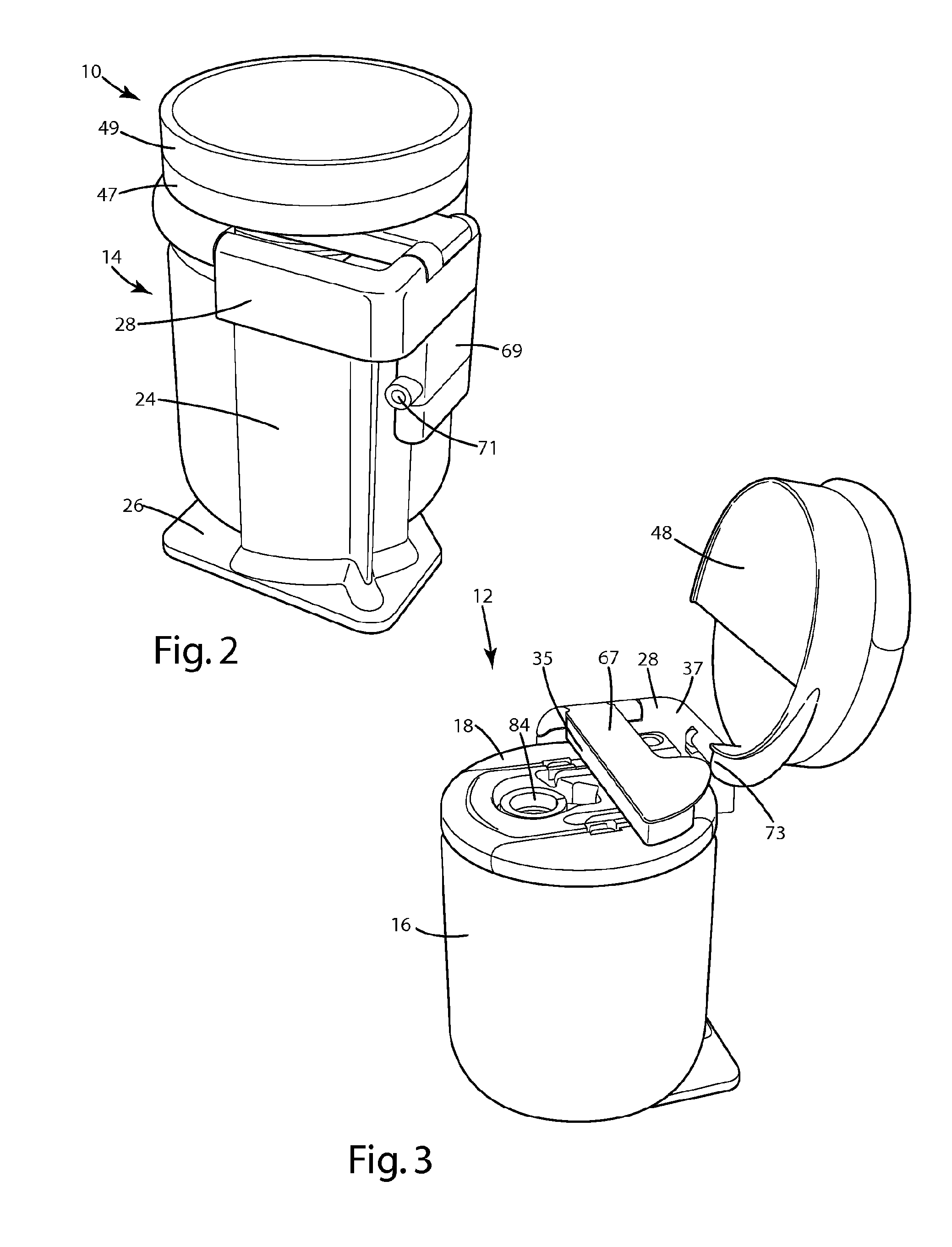
[0070]A point-of-use water treatment system according to one embodiment of the present invention is shown in FIGS. 1-10 and generally designated 10.

[0071]The embodiment illustrated in FIGS. 1-10 provides a WTS with a main housing 12 that is quickly and easily removable from a base portion 14. This enables a user to disconnect the main housing 12 from the base portion 14—which is commonly mounted in a particularly difficult to reach location, such as under the sink—and move it to a more comfortable location for maintenance purposes.

[0072]Referring to FIGS. 1 and 2, the main housing 12 includes a bucket 16 and a water mantle cover 18. The base portion 14 generally includes a backbone 24, a backbone base 26, and a backbone top 28. A water router 35 and an electronics tray 47 with display cover 49 also attach to the base in a hinged relationship, such that the water router 35 and electronics tray 47 can each be pivoted to open positions for easy removal of the main ho...

second embodiment

II. Second Embodiment

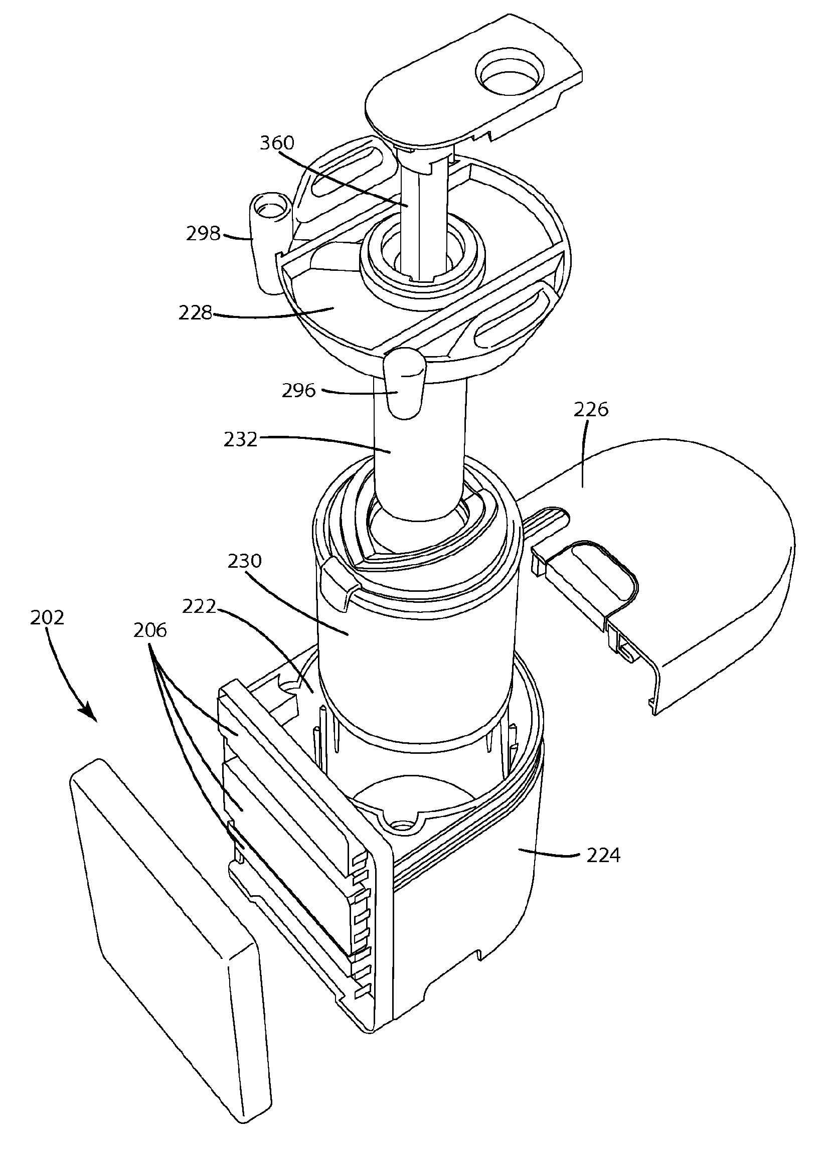
[0088]A WTS according to a second embodiment of the present invention is shown in FIGS. 11-26 and generally designated 200.

[0089]The embodiment illustrated in FIGS. 11-26 provides a large, aesthetic display 202 that attaches to a main housing 203 and can be configured with a variety of display options as desired. As shown in FIG. 11, the display 202 includes a front face 204 that covers the entire front of the WTS unit 200. The front face 204 forms the outer surface of an electronics “book,” shown in more detail in FIG. 21, that houses one or more removable electronic “bricks”206 between the front face 204 and a back plate 208. The front face 204 provides a display face for displaying a variety of information about the WTS 200 and components within the WTS 200. In one embodiment, the display face 204 is translucent or transparent, such that one or more displays, for example, LED displays, on the individual electronic bricks 206 are visible through the display fa...

third embodiment

III. Third Embodiment

[0111]A WTS according to a third embodiment of the present invention is shown in FIGS. 27-37 and generally designated 400.

[0112]The embodiment illustrated in FIGS. 27-37 provides a water treatment system that accommodates one or more easily removable and interchangeable filter modules 550. This embodiment allows a manufacturer or consumers to customize the filtration components of a WTS to meet the needs of a particular application. As shown in FIG. 27-31, the WTS 400 includes a pressure vessel 412, a water routing mantle 414, a center baffle 416, a filter assembly 420 and an optional disinfection assembly 422. In one embodiment, the pressure vessel 412 is a generally cylindrical container with a sidewall 424 including a top edge 426 that defines an opening 428. The sidewall 424 includes an outwardly extending groove 430 near the top edge 426.

[0113]The water routing mantle 414 of the WTS 400 is generally circular in shape and sized to fit inside the opening 428 ...


PUM

PropertyMeasurementUnit
mean particle diameteraaaaaaaaaa
angleaaaaaaaaaa
perimeteraaaaaaaaaa

Abstract

A water treatment system is capable of meeting the particular needs of a variety of water treatment system applications. For instance, the water treatment system may include a customizable display, multiple interchangeable filters and disinfection systems. In one embodiment, a vessel containing the filters and disinfection assembly can be easily removed from a base that supplies water to the vessel. In another embodiment, the water treatment system includes a plate that includes at least one electrical connection. One or more electronics bricks with sensors, displays and the like can be removably attached to the plate such that each electronics brick is in electrical communication with said brick. In another embodiment, the water treatment system incorporates one or more stackable and interchangeable filter blocks that direct water flowing into the vessel through each filter media.

Description

[0001]The present invention is directed to water treatment system (WTS) units, and more particularly to point-of-use home or commercial WTS units.[0002]Water treatment systems are commonly used to treat water in a distribution system. A water treatment system removes pathogens, chemical contaminates, and turbidity from water that is used for human consumption. Water treatment systems may employ filtration components, ion exchange components, ultraviolet radiation components and the like to treat water as it flows through the water treatment system from a water supply to a point of distribution, for example, a faucet in a building.[0003]Conventional water treatment systems connect a municipal or private pressurized water supply to a water distribution system. For example, an under-counter water treatment system, of the type used in residences or businesses, provides fluid communication between a pressurized water supply line and a faucet. As the water flows through the system, the sy...

Claims


Application Information

Patent Timeline
Patent Type & Authority Applications(United States)
IPC IPC(8): C02F9/12C02F1/32B01D35/04C02F1/28
CPCC02F1/001C02F1/006C02F1/008C02F1/283C02F1/32C02F2303/04C02F2201/003C02F2201/006C02F2201/3223C02F2209/00C02F2301/08C02F9/005C02F9/20C02F1/00C02F1/28B01D35/04B01D35/147B01D36/00C02F1/325C02F2201/32
Inventor LAUTZENHEISER, TERRY L.MILES, MICHAEL E.VECZIEDINS, KARLISCONRAD, KENNETH E.CONRAD, AUDREY
Owner ACCESS BUSINESS GRP INT LLC
Why Eureka
Try Eureka