
Positioning method of movable apparatus and positioning system

Inactive Publication Date: 2012-05-31
ASUSTEK COMPUTER INC
View PDF4 Cites 14 Cited by
  • Summary
  • Abstract
  • Description
  • Claims
  • Application Information

AI Technical Summary

Benefits of technology

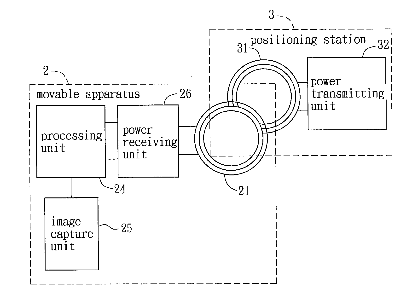
[0011]The movable apparatus is charged by the electromagnetic induction, instead of the conventional contact method, which enlarges the detectable area, decreases the positioning missing rate and improves positioning efficiency.

Problems solved by technology

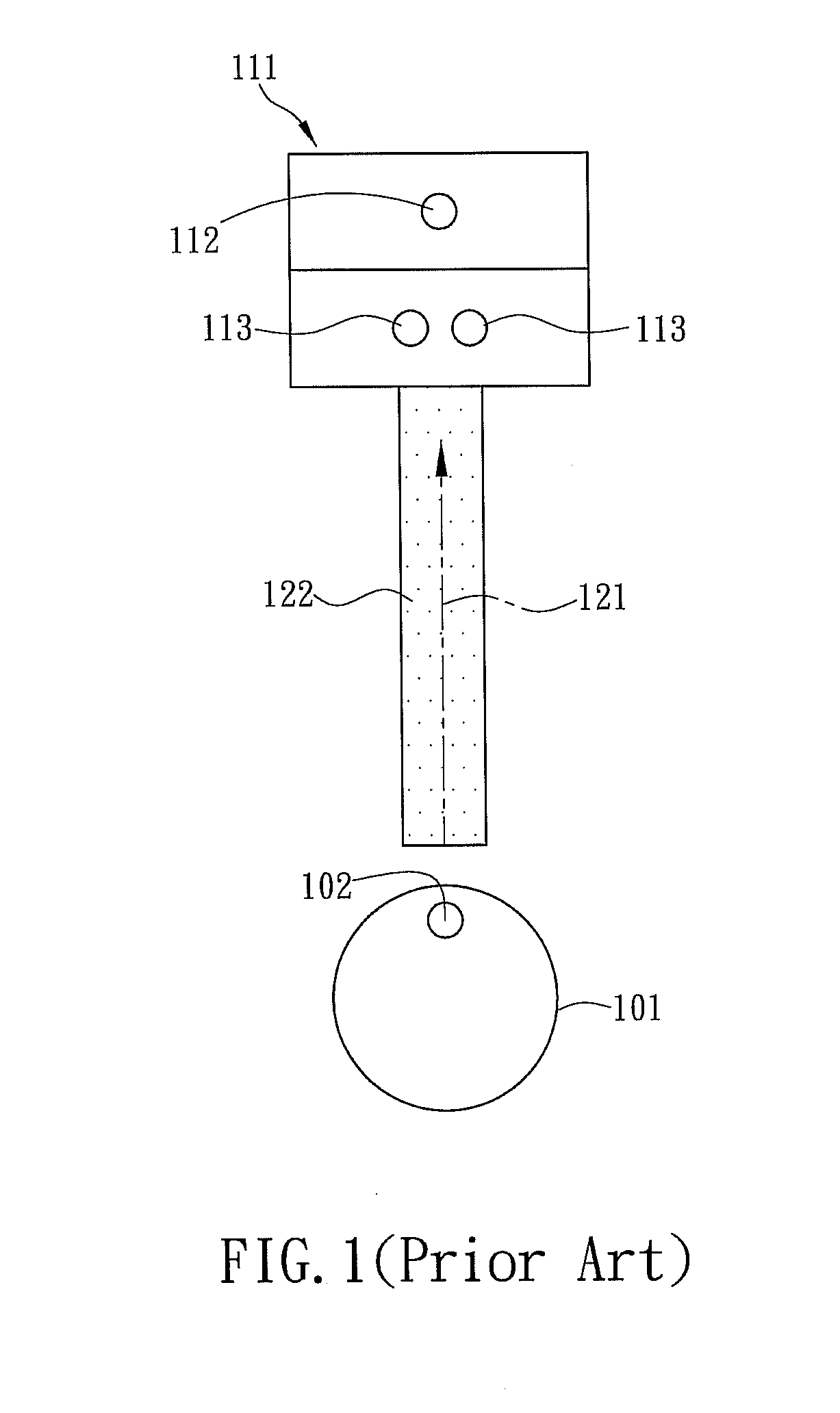
However, due to the detectable area 122 that emitted by IR in the current position method is limited; the positioning process is easy to be missed.
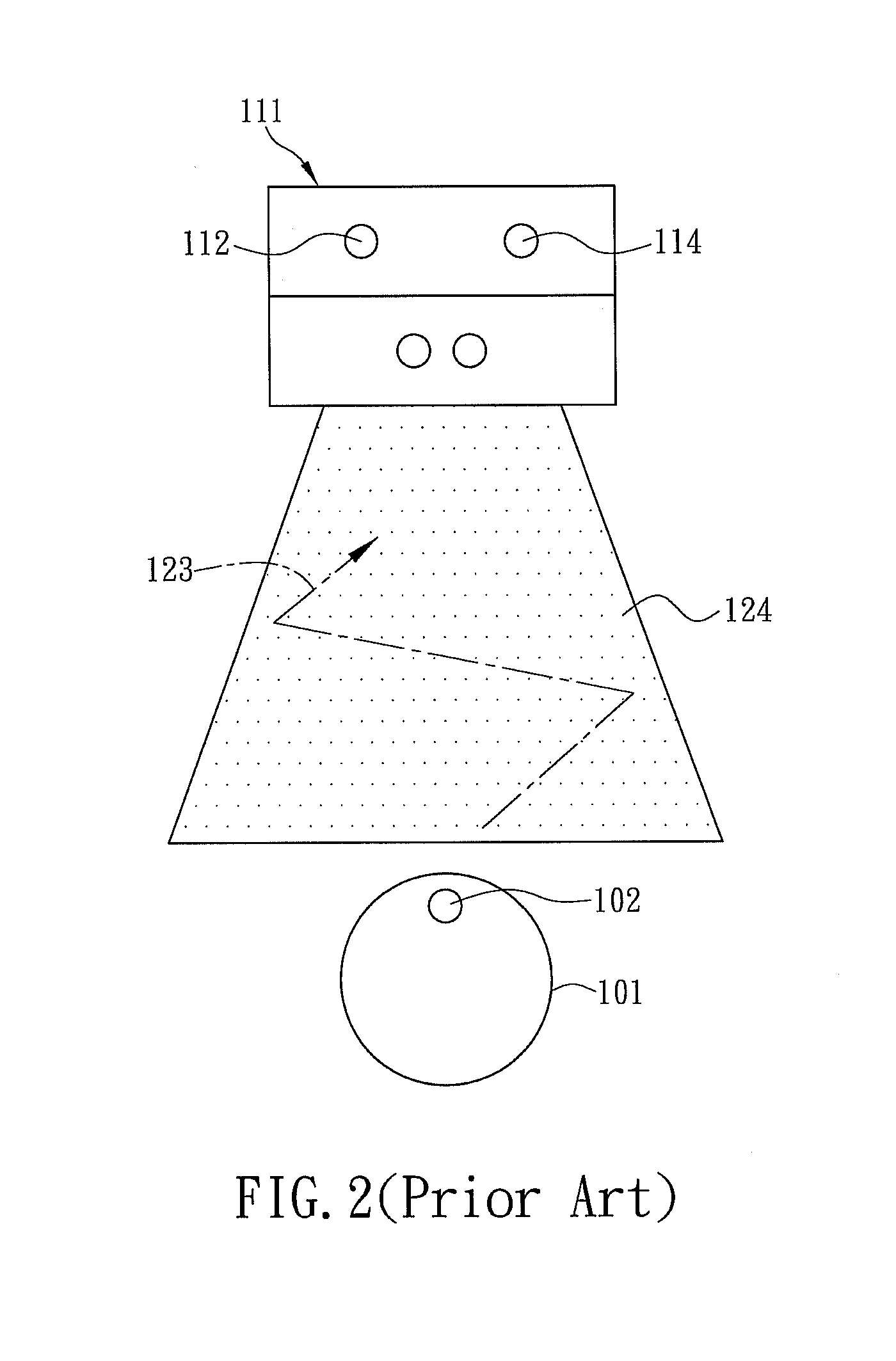
However, in the second positioning process, the derious moving path of the movable electronic device 101 is long, and thus the positioning time increases.
Additionally, the elements that equipped on the movable electronic devices are not fully used in conventional positioning methods.
Furthermore, since the conventional charging method is achieved by physical contact, the charging station should be leaned on a wall or a pillar to withstand impact while the movable electronic device is physically contact the charging station to be charged and ensures that the electrodes contact the movable electronic device firmly, which limits the location chosen and the positioning process of the charging station.

Method used


Image

  • Positioning method of movable apparatus and positioning system
  • Positioning method of movable apparatus and positioning system
  • Positioning method of movable apparatus and positioning system

Examples


Embodiment Construction

[0019]A positioning method of a movable apparatus in an embodiment is illustrated with relating figures, and the same symbols denote the same components.

[0020]FIG. 3 is a flow chart showing steps of a positioning method of a movable apparatus in an embodiment, and FIG. 4 is a block diagram showing a positioning system in an embodiment. The positioning system includes a movable apparatus 2 and a positioning station 3. The movable apparatus 2 includes a processing unit 24 and an inducting coil 21 electrically connected to the processing unit 24. The positioning station 3 includes a power transmitting unit 32 and a transmitting coil 31 connected to the power transmitting unit 32. The positioning method is applied to the movable apparatus 2 and the positioning station 3. The positioning method includes following steps: transmitting a testing signal via the transmitting coil 31 (Step S01), inducting the testing signal from the transmitting coil 31 via the inducting coil 21 (Step S02), me...


PUM


Abstract

A positioning method is applied to a movable apparatus and a positioning station. The movable apparatus includes an inducting coil, and the positioning station includes a transmitting coil. The positioning method includes the following steps: transmitting a testing signal via the transmitting coil, inducting the testing signal from the transmitting coil via the inducting coil, measuring an induction value of the inducting coil and driving the movable apparatus to move towards the positioning station according to the induction value.

Description

CROSS REFERENCE TO RELATED APPLICATIONS[0001]The Non-provisional application claims priority to U.S. provisional patent application with Ser. No. 61 / 418,156 filed on Nov. 30, 2010. This and all other extrinsic materials discussed herein are incorporated by reference in their entirety.BACKGROUND OF THE INVENTION[0002]1. Field of Invention[0003]The invention relates to a positioning method and, more particularly, to a positioning method of a movable apparatus and a positioning system.[0004]2. Related Art[0005]A movable electronic device may automatically enter a station for charging. Conventionally, the movable electronic device has an infrared radiation (IR) sensor and is charged by a contacting charging method. FIG. 1 is a schematic diagram showing that a conventional movable electronic device enters a station automatically for charging. The movable electronic device 101 includes an IR sensor 102, and the charging station 111 includes an IR sensor 112 and two metal electrodes 113 fo...

Claims


Application Information

Patent Timeline
IPC IPC(8): H01F38/14G01R27/28
CPCH01F38/14
Inventor LAI, MING-IULIN, SHIH-CHI
Owner ASUSTEK COMPUTER INC
Learn More