

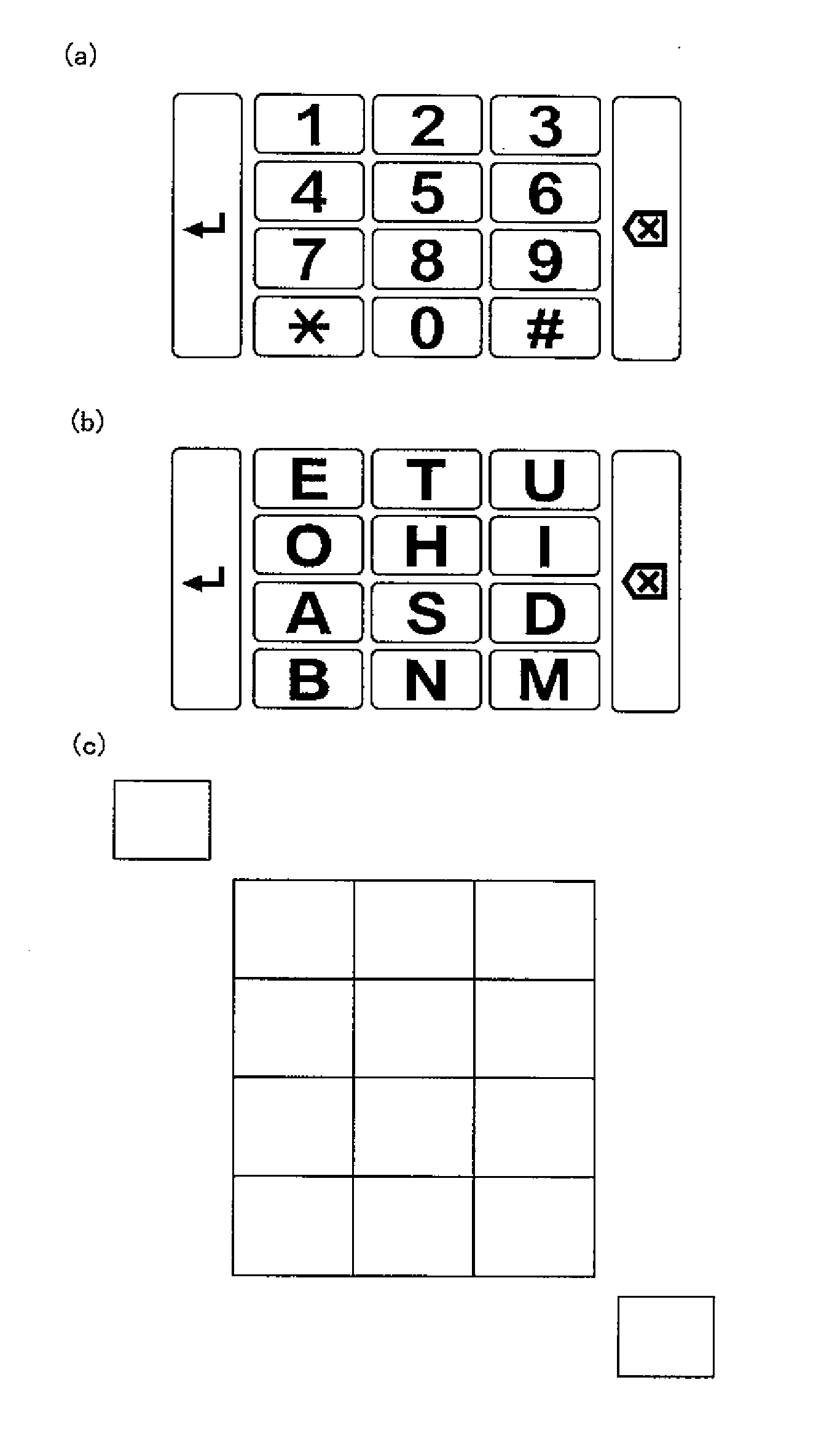
Digitizer for a fingertip tactile-sense input device
- Summary
- Abstract
- Description
- Claims
- Application Information
AI Technical Summary
Benefits of technology
Problems solved by technology
Method used
Image

Examples
first embodiment
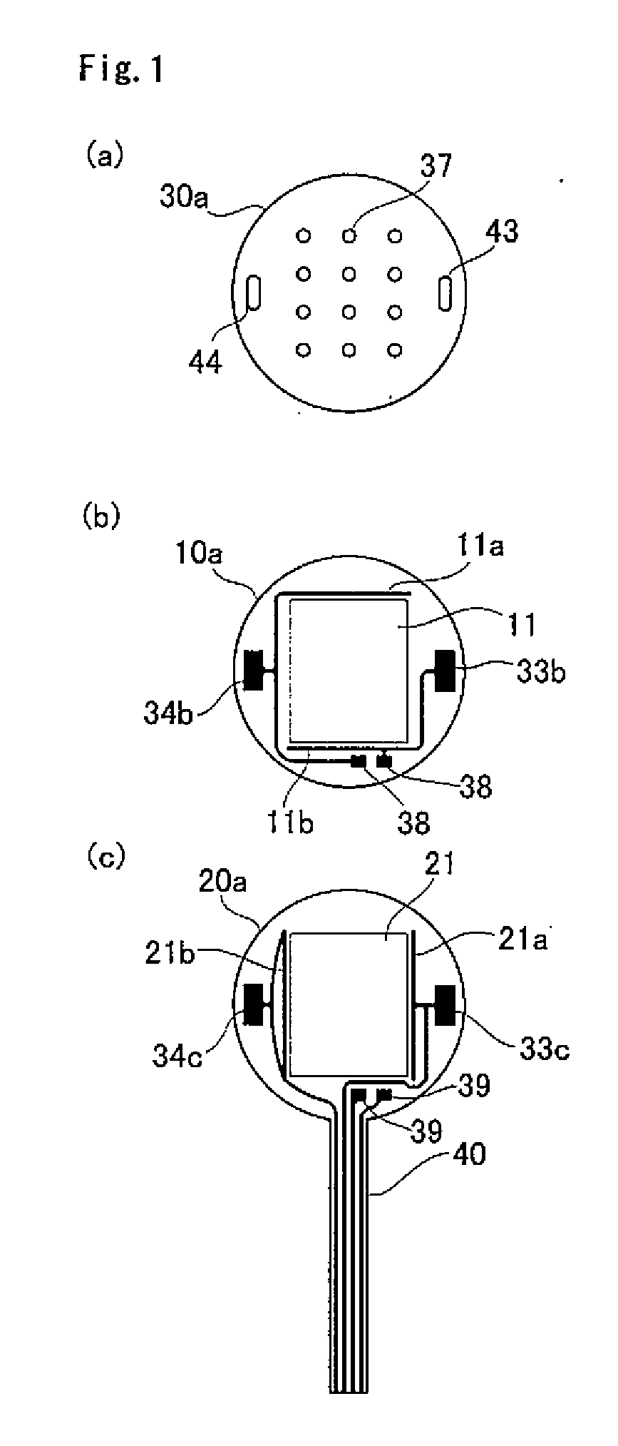
[0135]FIG. 1 is a top view of a digitizer for a fingertip tactile-sense input device of the present invention. This digitizer comprises a first resistive sheet (10a) that is shown in FIG. 1(b), and a second resistive sheet (20a) that is shown in FIG. 1(c). In order to show the relationship with the keys, a top surface sheet (30a) is also shown as a reference in FIG. 1(a).
[0136]The top surface sheet (30a), the first resistive sheet (10a) and the second resistive sheet (20a) are shown in the state as seen from the operating side, and are shown in a transparent state where the wiring pattern that appears on the second resistive sheet (20a) is located on the front side in the figure, however, the wiring pattern that appears on the first resistive sheet (10a) is located on the rear side of the drawing.
[0137]Moreover, in the state shown in the figure, the first resistive sheet (10a) overlaps the second resistive sheet (20a), with square connective pads (38, 39) being electrically connecte...
second embodiment
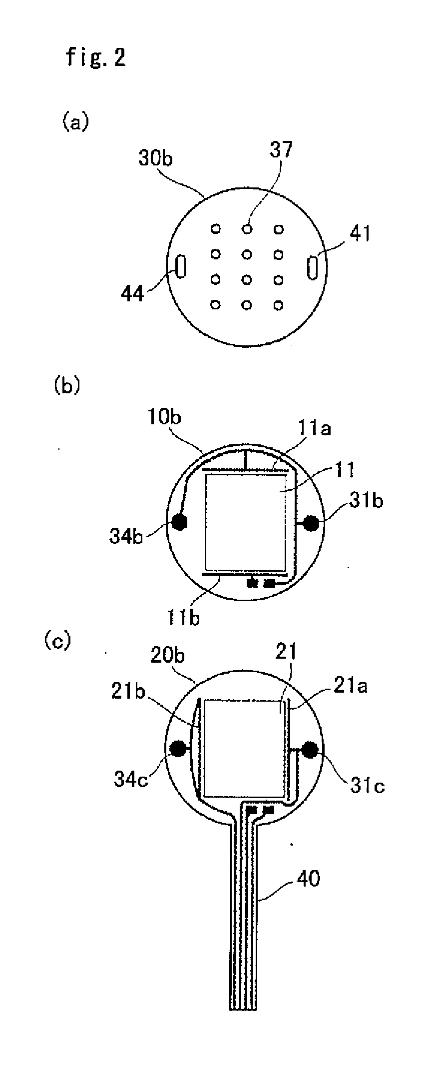
[0151]FIG. 2 is a top view of a digitizer for a fingertip tactile-sense input device of the present invention, and shows a first resistive sheet (10b) and second resistive sheet (20b). Similarly, the top surface sheet (30b) is also shown. The parts that are different from the embodiment shown in FIG. 1 will be explained below.
[0152]On both the first resistive sheet (10b) and second resistive sheet (20b) there is a first right contact (31b) and second right contact (31c) that are separated to the right from the control areas (11, 21) and are arranged such that they face each other to form a right switch (31), with the first right contact (31b) being connected to a top edge electrode (11a) and the second right contact (31c) being connected to a right side electrode (21a).
[0153]On both the first resistive sheet (10b) and second resistive sheet (20b) there is a first left contact (34b) and second left contact (34c) that are separated to the left from the control areas (11, 21) and are a...
third embodiment
[0155]FIG. 3 is a top view of a digitizer for a fingertip tactile-sense device of the present invention, and shows a first resistive sheet (10c) and second resistive sheet (20c). Similarly, a top surface sheet (30c) is also shown. The parts that are different from the embodiment shown in FIG. 1 will be explained below. In this embodiment, there are two right switches and two left switches, with keys being provided that correspond to the four switches.
[0156]On both the first resistive sheet (10c) and second resistive sheet (20c), there is a first upper right contact (31b) and second upper right contact (31c) that are located in specified positions that are separated to the upper right from the control areas (11, 21) and arranged so that they face each other to form an upper right switch (31), with the first upper right contact (31b) being connected to an top edge electrode (11a), and the second upper right contact (31c) being connected to a right edge electrode (21a).
[0157]On both th...
PUM
 Abstract
Description
Claims
Application Information