Device for Delivering Liquid Medicament
- Summary
- Abstract
- Description
- Claims
- Application Information
AI Technical Summary
Benefits of technology
Problems solved by technology
Method used
Image

Examples
Embodiment Construction
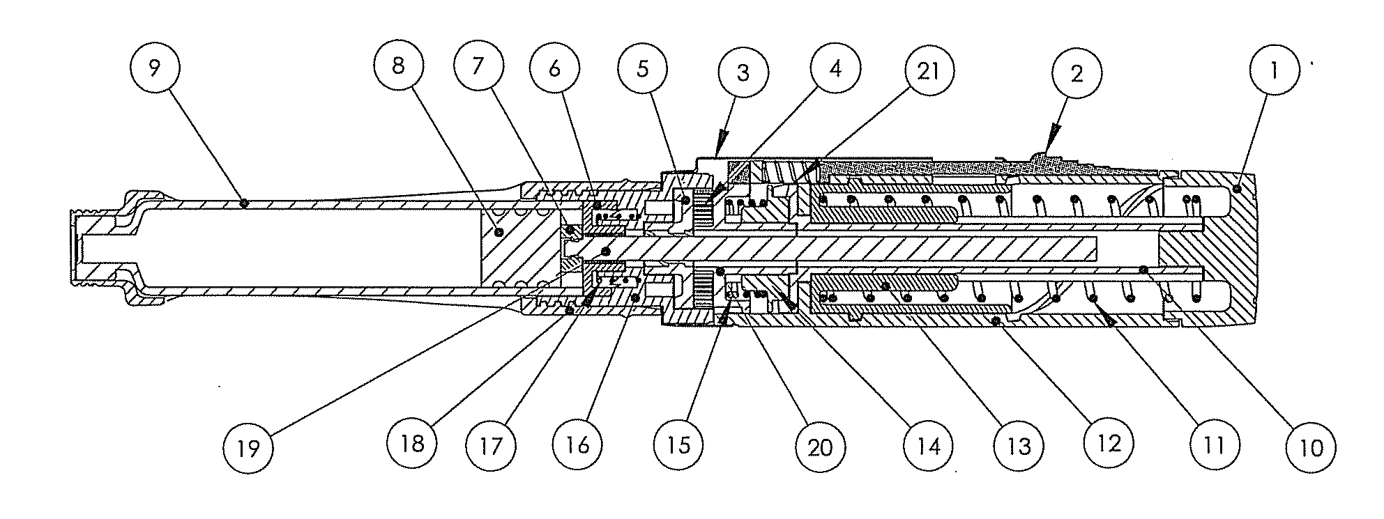
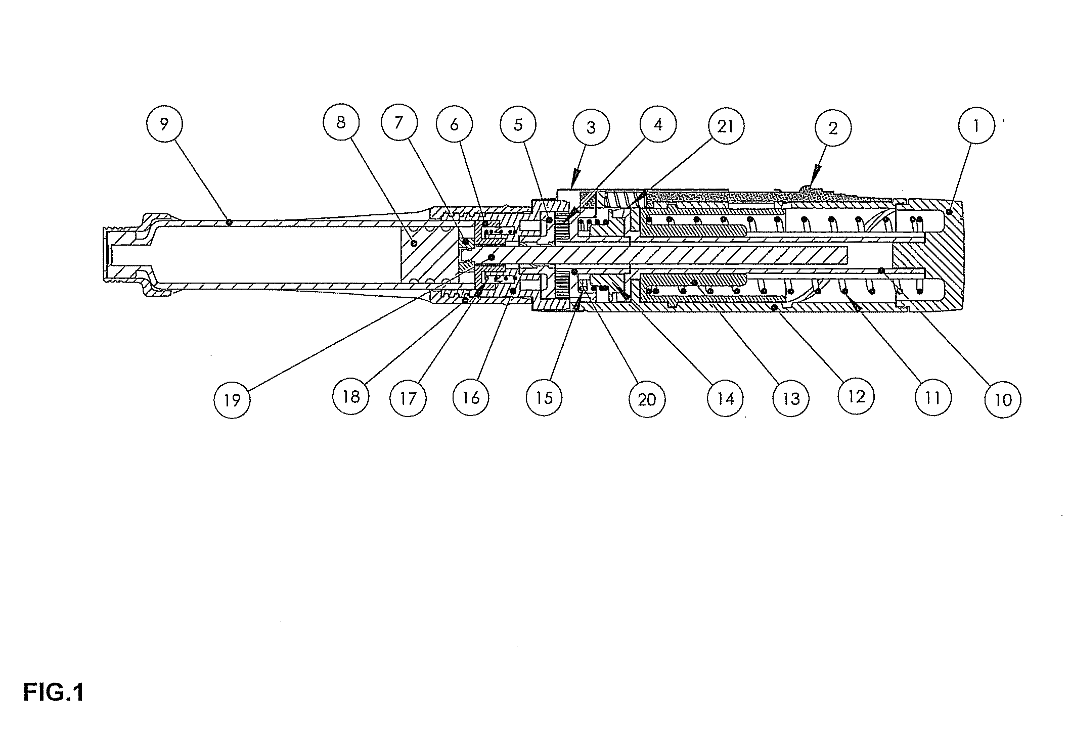
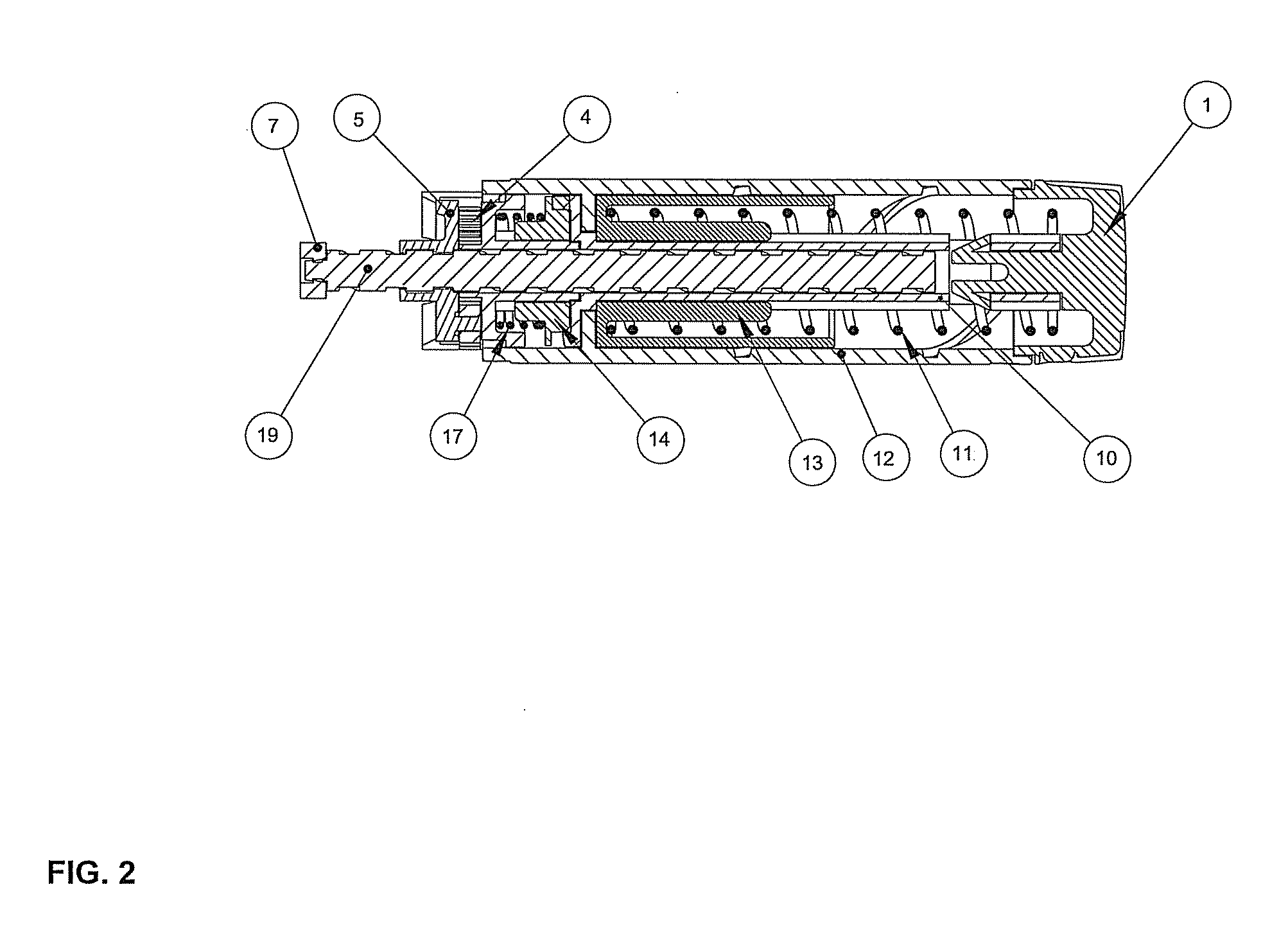
[0036]In the present detailed description, the terms “front side” or “front” and “rear side” or “rear” are used to define the direction of different components. In the following text, “front side” or “front” refer to the physical end of the invention where the medicament is delivered out from the device, and also constitutes the end where an external component can be connected onto the device. It could be an injection needle, which is screwed fitted or snap-locked onto the device, or a mouth piece which transforms the pressurized liquid medicament into a spray or an aerosol. It could also be another kind of orifice, as for example a component equipped with a hole, which is pressed against the skin, where the fluid pressure of the liquid medicament is sufficiently high to enable the liquid to penetrate the patient's skin without using a penetrating needle, whereby the device in this embodiment constitutes a needle-free injector for medicament. In the following text, “rear side” or “r...
PUM
 Abstract
Description
Claims
Application Information