
Method Of Control Of Rotation of Spindle and Control System Of Machine Tool

Active Publication Date: 2012-05-31
MAKINO MILLING MASCH CO LTD
View PDF8 Cites 8 Cited by
  • Summary
  • Abstract
  • Description
  • Claims
  • Application Information

AI Technical Summary

Benefits of technology

[0006]In the above rotational control method, the spindle rotational speed change data is stored linked with the machining conditions and stability limit data, so at the time of actual machining, it is possible to select the spindle rotational speed change data giving less vibration from the instructed spindle rotational speed and machining conditions and the stored stability limit data. Further, the selected spindle rotational speed change data is used as the basis to change the rotational speed of the spindle while machining, so there is resistance to chatter vibration.
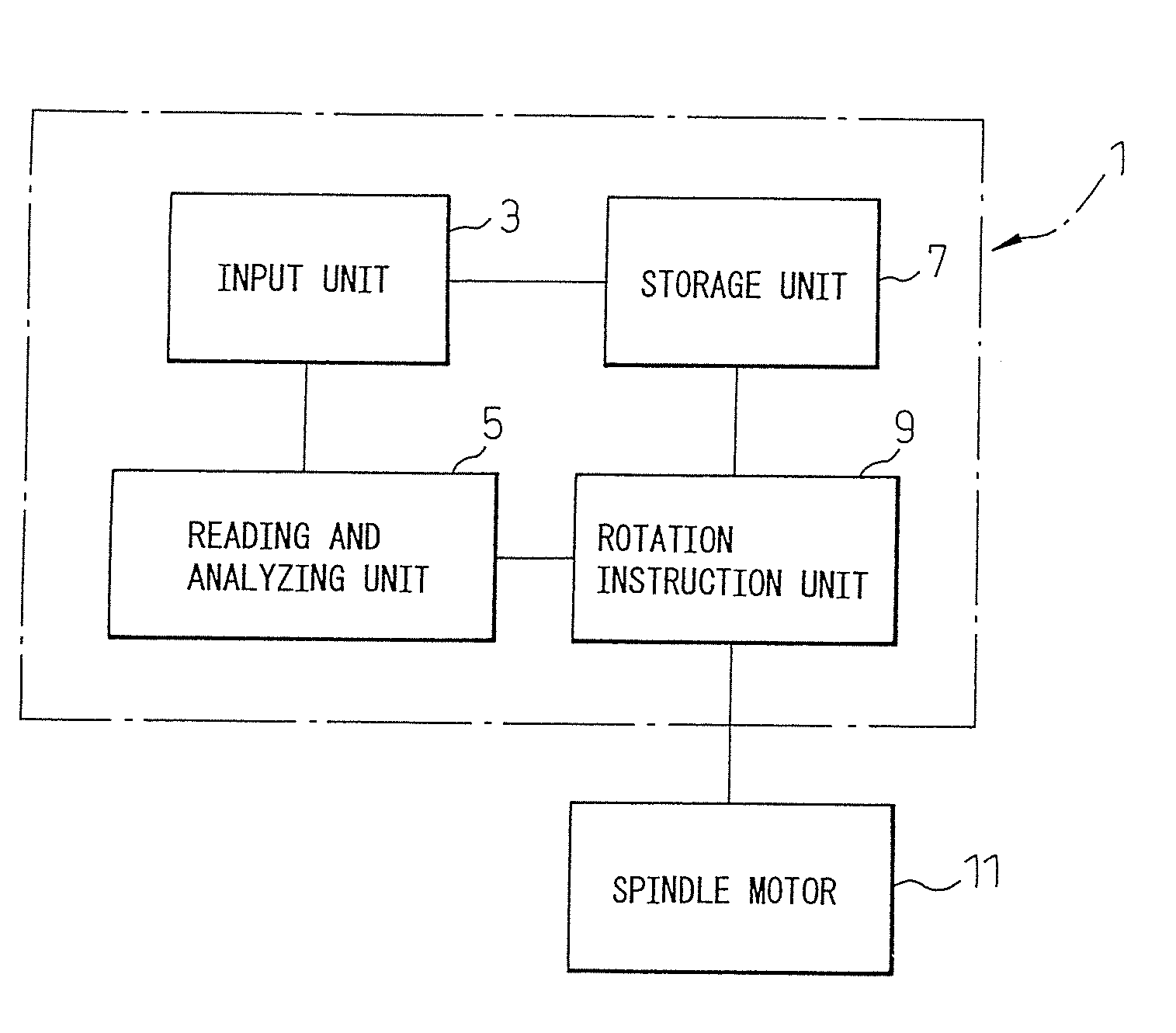
[0010]Further, according to the present invention, there is provided a control system of a machine tool which makes a tool and workpiece move relative to each other and machines a workpiece, the control system of a machine tool comprising a storage unit which stores a plurality of spindle rotational speed change data linked with machining conditions and stability limit data and with a rotation instruction unit which selects, from an instructed spindle rotational speed and machining conditions and stored stability limit data, spindle rotational speed change data giving less vibration and uses the selected spindle rotational speed change data as the basis to change a rotational speed of a spindle.
[0012]According to the present invention, it is possible to select prestored spindle rotational speed change data in accordance with the instructed rotational speed and machining conditions and to use the selected spindle rotational speed change data as the basis to change the spindle rotational speed and thereby suppress chatter vibration, so there is no need to prepare a special tool with variable pitch cutting edges and there is no need to detect the chatter vibration, so the costs of the tools and machine tool become smaller. Further, the spindle rotational speed is changed based on the desired spindle rotational speed instructed by the machining program, so it is possible to suppress chatter vibration without greatly changing the spindle rotational speed from the instructed spindle rotational speed.

Problems solved by technology

There was the problem of increased costs of the tool.
There was therefore the problem of increased costs of the machine tool.

Method used


Image

  • Method Of Control Of Rotation of Spindle and Control System Of Machine Tool
  • Method Of Control Of Rotation of Spindle and Control System Of Machine Tool
  • Method Of Control Of Rotation of Spindle and Control System Of Machine Tool

Examples


first embodiment

[0023]The method of control of rotation of a spindle device according to a first embodiment of the present invention will be explained.

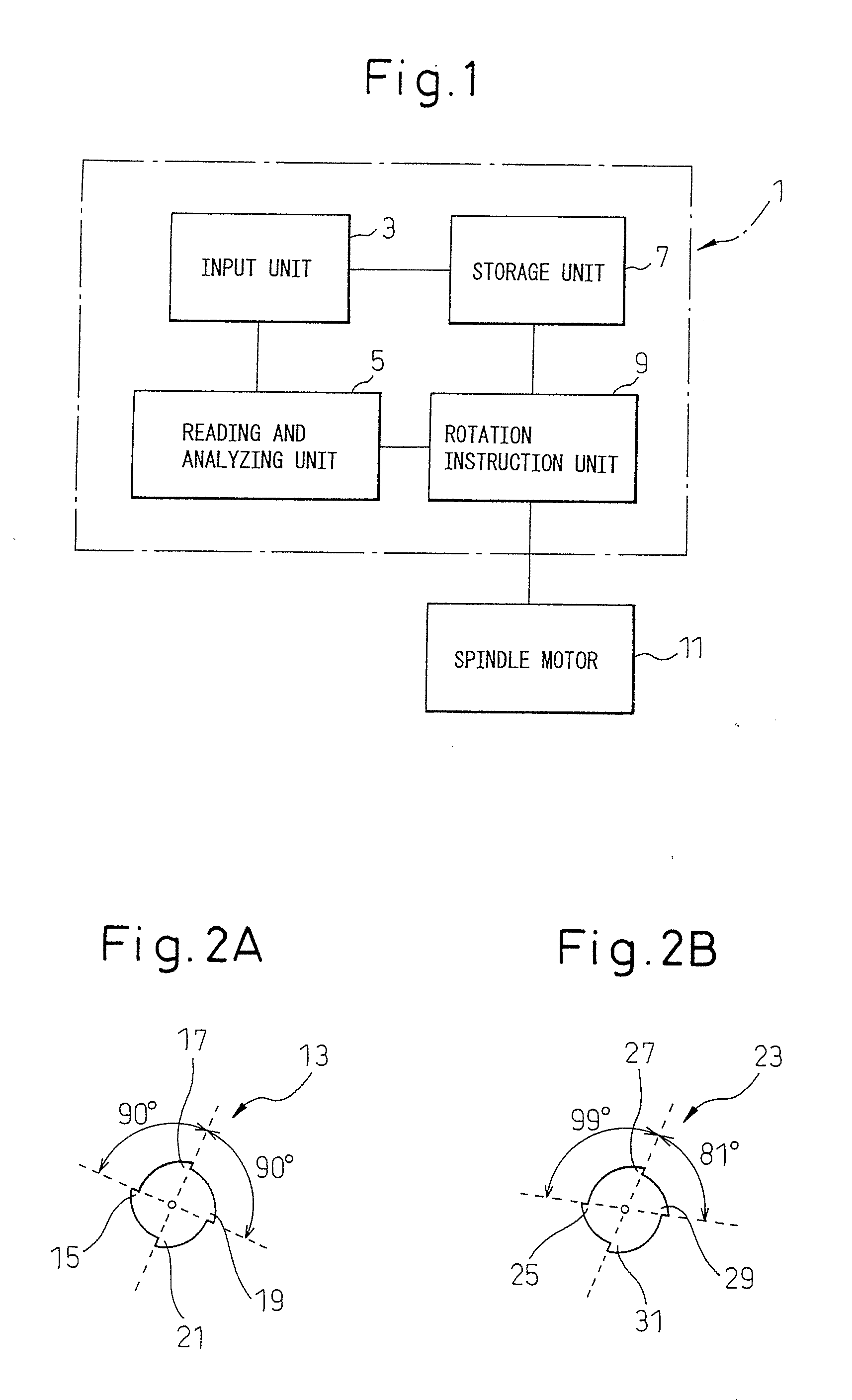
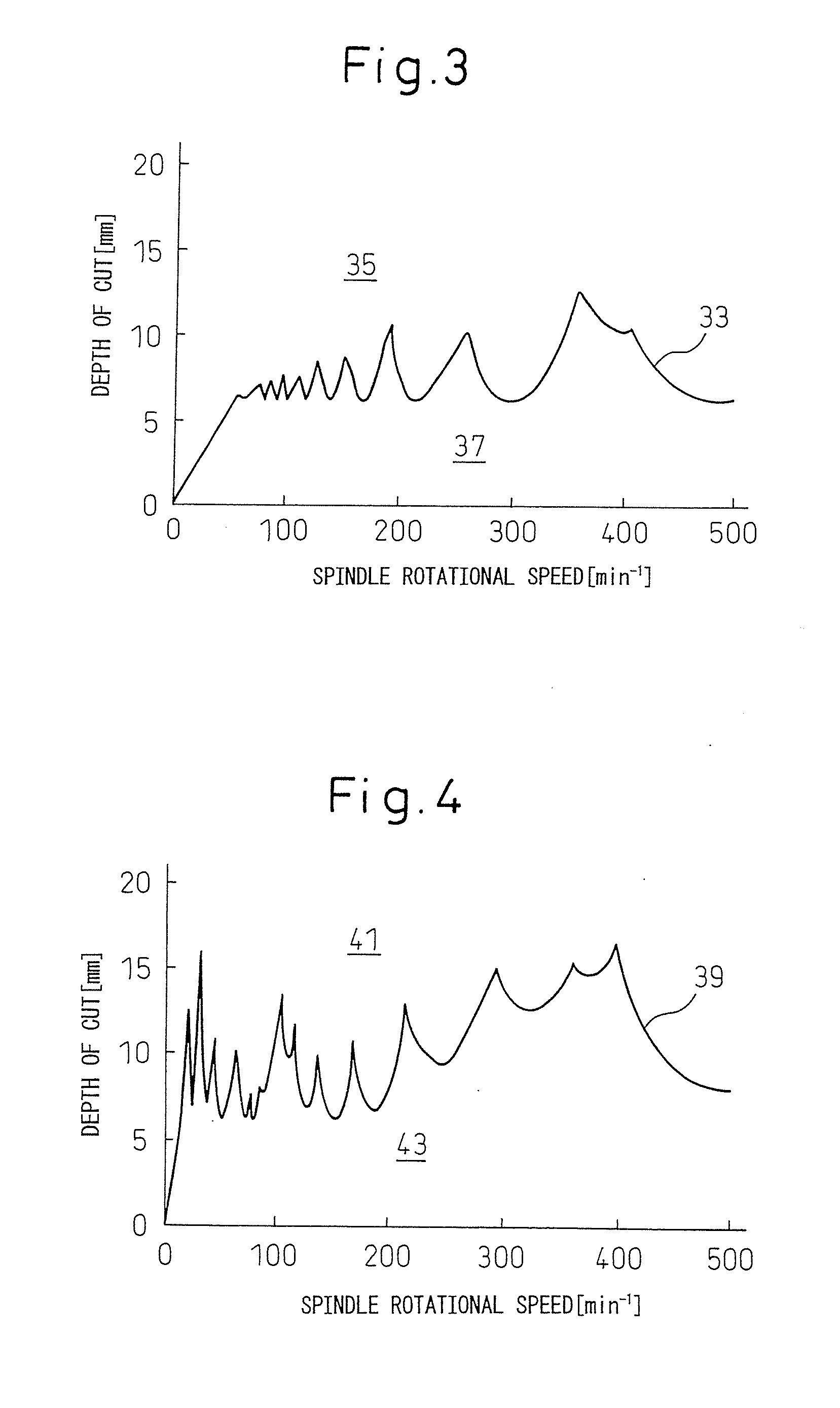
[0024]First, in advance, the storage unit 7 stores spindle rotational speed change data, which determines how to change a rotational speed of a spindle in accordance with an instructed speed, linked various machining conditions and stability limit data and stores the plurality of data in a map form. Various formats of spindle rotational speed change data may be considered, but in the present embodiment, it is made data for changing the rotational speed of the spindle so that the timings at which cutting edges of an equal pitch cutting edge tool attached to the spindle strike a workpiece become the timings by which a workpiece is struck when using a tool of variable pitch cutting edges.

[0025]FIG. 3 is a stability limit graph when using an end mill 13 of equal pitch cutting edges of FIG. 2A for machining by a tool diameter of 50 mm and a feed rate of 1...

second embodiment

[0030]Then, the method of control of rotation of a spindle device according to a second embodiment of the present invention will be explained.

[0031]In the same way as the first embodiment, the method selects, from the data stored in the storage unit 7, the stability limit data so that the depth of cut at the instructed spindle rotational speed enters the stable region and selects spindle rotational speed change data by which cutting edges of the tool strike the workpiece at the timings of a pitch angle corresponding to the selected stability limit data. At this time, the first embodiment performed control so that the change in spindle rotational speed drew a square wave 51 such as in FIG. 5, but the second embodiment performs control so that the change in the spindle rotational speed draws a secondary curve 57 such as in FIG. 6.

[0032]At that time, the secondary curve 57 should be determined so that the area of the part surrounded by the instructed rotational speed 45 and square wave...

third embodiment

[0033]Then, the method of control of rotation of a spindle device according to a third embodiment of the present invention will be explained.

[0034]First, in advance, spindle rotational speed change data, which determines how to change a rotational speed of a spindle in accordance with an instructed speed, is linked with the number of cutting edges of a tool and pitch angle and stored in the storage unit 7. When the number of cutting edges of a tool and the pitch angle giving a small chatter vibration are known, the desired number of cutting edges and pitch angle are input from the input unit 3 by the machining program and parameters. The rotation instruction unit 9 selects the spindle rotational speed change data from the input number of cutting edges and pitch angle and uses the spindle rotational speed change data selected in the same way as the above-mentioned first or second embodiment as the basis to control the rotational speed of the spindle motor 11.


PUM

PropertyMeasurementUnit
Speedaaaaaaaaaa
Stabilityaaaaaaaaaa

Abstract

A method of control of rotation of a spindle device and a control system of a machine tool which enable machining without generation of chatter vibration without using special tools of variable pitch cutting edges or chatter vibration detecting means. The method of control of rotation of a spindle device and control system of a machine tool according to the present invention store spindle rotational speed change data, which determines how to change a rotational speed of a spindle in accordance with an instructed speed, linked with machining conditions and stability limit data, select, from an instructed spindle rotational speed and machining conditions and the stored stability limit data, spindle rotational speed change data giving less vibration, and use the selected spindle rotational speed change data as the basis to change the rotational speed of the spindle.

Description

TECHNICAL FIELD[0001]The present invention relates to a method of control of rotation of a spindle which is made to rotate while holding a tool and to a control system of a machine tool.BACKGROUND ART[0002]In machine tools, when using a rotary tool to machine a workpiece, chatter vibration sometimes occurs. If chatter vibration occurs, it has a detrimental effect on machining, so to obtain high precision machining, chatter vibration has to be suppressed. As a method for suppressing chatter vibration, there is the method of making the pitch of the cutting edges of the rotary tool a variable one. Japanese Patent Publication (A) No. 2007-83329 discloses a rotary cutting tool by which a single tool can be used to form a variable pitch tool of various patterns. Further, Japanese Patent Publication (A) No. 2007-44852 discloses to detect chatter vibration and control the rotational speed of a spindle to a rotational speed where chatter vibration does not occur.[0003]The prior art using a v...

Claims


Application Information

Patent Timeline
IPC IPC(8): B23Q15/12
CPCB23C2210/282B23C2250/16B23Q17/0976Y10T82/2595G05B2219/41121G05B2219/41207Y10T409/304312G05B19/404
Inventor MIYAMOTO, RYOICHINAGAHARA, YUYA
Owner MAKINO MILLING MASCH CO LTD
Learn More