Vehicle, abnormality determination method for internal combustion engine, and abnormality determination device for internal combustion engine

US20120136552A1Active Publication Date: 2012-05-31TOYOTA JIDOSHA KK +1

Image

  • Vehicle, abnormality determination method for internal combustion engine, and abnormality determination device for internal combustion engine
  • Vehicle, abnormality determination method for internal combustion engine, and abnormality determination device for internal combustion engine
  • Vehicle, abnormality determination method for internal combustion engine, and abnormality determination device for internal combustion engine

Examples


Embodiment Construction

[0024]An embodiment of the invention will be described below with reference to the appended drawings. In the explanation below, like components are assigned with like reference numerals. These components have same names and functions. Therefore, detailed explanation thereof is not repeated.

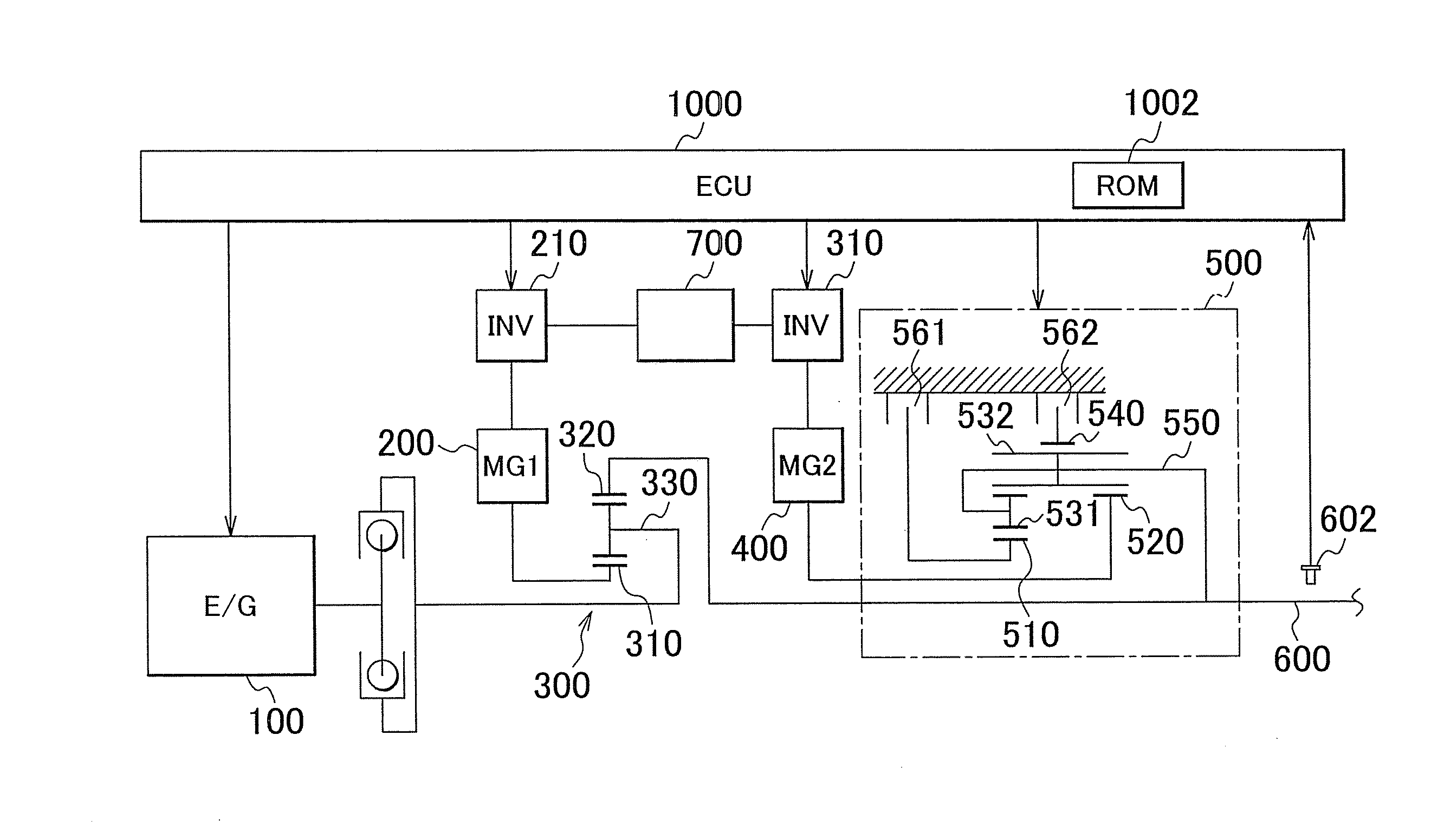
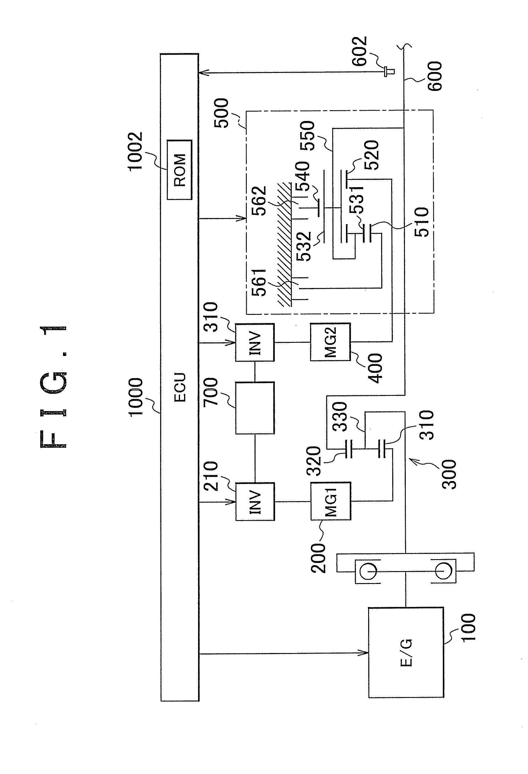
[0025]A power train of a hybrid vehicle will be explained below with reference to FIG. 1. As shown in FIG. 1, the power train is constituted mainly by an engine 100, a first motor generator (MG1) 200, a power distribution mechanism 300 that combines or distributes the torque between the engine 100 and the first motor generator 200, a second motor generator (MG2) 400, and a transmission 500.

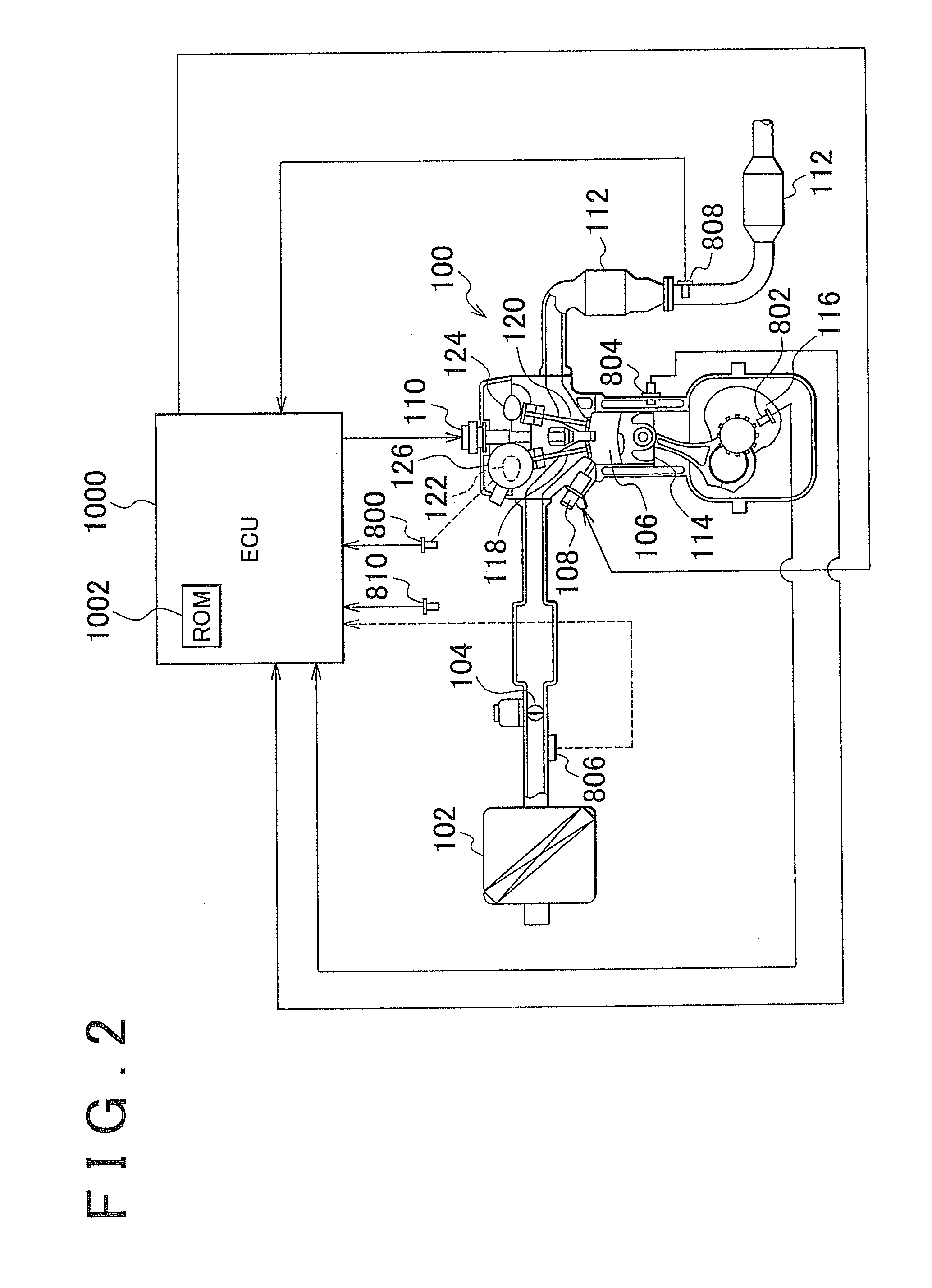
[0026]The engine 100 is a conventional power apparatus that outputs power generated by combustion of fuel. The engine is configured such that the operation state such as a throttle opening degree (air intake amount), a fuel supply amount, and an ignition timing can be electrically controlled. This control is per...


PUM


Abstract

A vehicle including an internal combustion engine provided with a plurality of cylinders, and a control unit that determines that an abnormality of the internal combustion engine has occurred when an atmospheric pressure has a first value and an operation state represented by at least one of an output shaft revolution speed and a load of the internal combustion engine is within a preset region and determines that an abnormality of the internal combustion engine has occurred when the atmospheric pressure has a second value that is lower than the first value and the operation state is outside the region.

Description

INCORPORATION BY REFERENCE[0001]The disclosure of Japanese Patent Application No. 2010-266742 filed on Nov. 30, 2010 including the specification, drawings and abstract is incorporated herein by reference in its entirety.BACKGROUND OF THE INVENTION[0002]1. Field of the Invention[0003]The invention relates to a vehicle, an abnormality determination method for an internal combustion engine, and an abnormality determination device for an internal combustion engine, and more particularly to a technique for changing an operation region that determines an abnormality according to the atmospheric pressure.[0004]2. Description of Related Art[0005]An internal combustion engine is available in which fuel is burned in cylinders. In the internal combustion engine, the fuel is not necessarily always burned normally. For this reason, a variety of abnormality determination functions are incorporated in a control device that controls the internal combustion engine.[0006]Japanese Patent Application P...

Claims


Application Information

Patent Timeline
31 May 2012
Publication
US20120136552A1
IPC
F02D45/00
CPC
F02D41/22; F02D2200/1002; Y02T10/40; F02D2200/703; F02D2200/101
Inventors
KATO, TOSHIKAZU; FUJITSU, YUSUKE