TCP window size performance optimization in wireless networks

a technology of window size and wireless network, applied in the direction of digital computers, wireless network protocols, instruments, etc., can solve problems such as radio resources being wasted

Active Publication Date: 2012-05-31
VERIZON PATENT & LICENSING INC
View PDF7 Cites 27 Cited by
  • Summary
  • Abstract
  • Description
  • Claims
  • Application Information

AI Technical Summary

Problems solved by technology

However, a larger window size may result in wasted radio resources.

Method used


Image

  • TCP window size performance optimization in wireless networks
  • TCP window size performance optimization in wireless networks
  • TCP window size performance optimization in wireless networks

Examples


Embodiment Construction

[0006]The following detailed description of embodiments refers to the accompanying drawings. The same reference numbers in different drawings may identify the same or similar elements. Also, the following detailed description does not limit the invention.

[0007]Implementations described herein may provide systems and / or methods that optimize Transmission Control Protocol (TCP) performance in a wireless network. Optimizing the TCP performance may increase overall throughput in the wireless network.

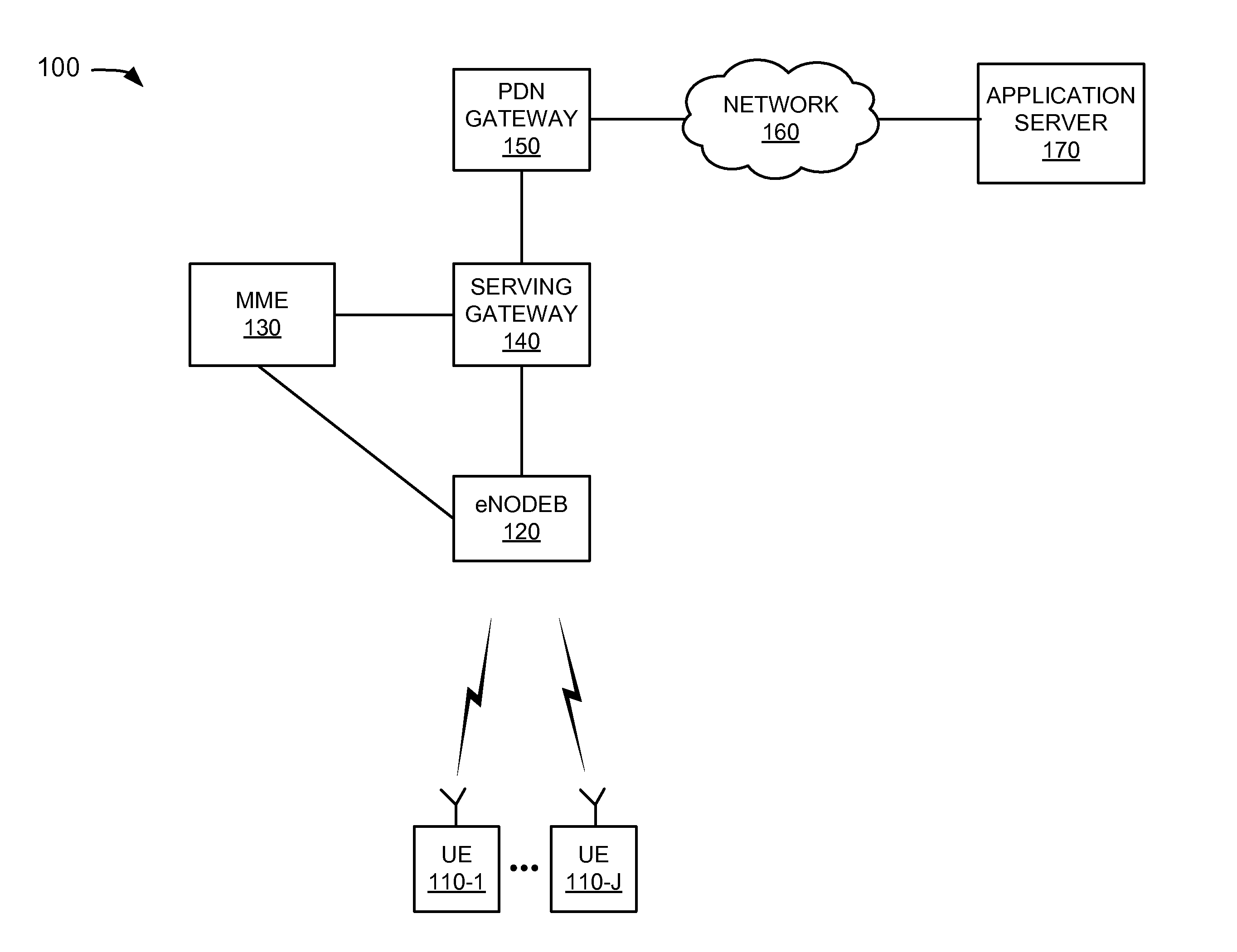
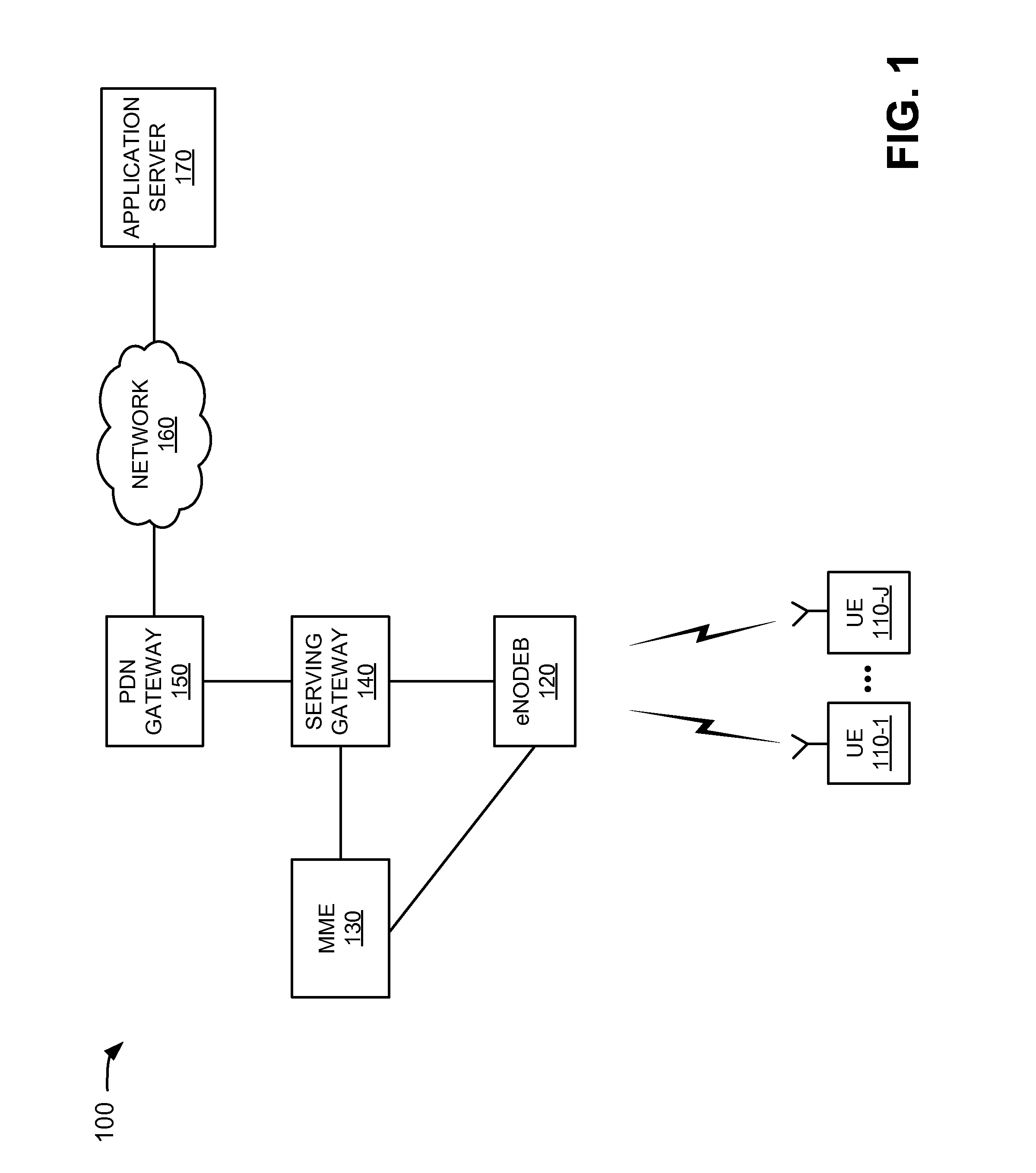
[0008]FIG. 1 is a diagram of an example network 100 in which systems and methods described herein may be implemented. Network 100 may include a group of user equipment (UE) 110-1 through 110-J (J≧1) (referred to collectively, and in some instances individually, as “user equipment 110”), an evolved NodeB (eNodeB) 120, a mobility management entity 130, a serving gateway 140, a packet data network (PDN) gateway 150, a network 160, and an application server 170. eNodeB 120, mobility management e...


PUM


Abstract

A system may include user equipment. The user equipment may determine a group of first Transmission Control Protocol (TCP) window size values based on different information relating to a wireless network, and determine a second TCP window size value based on the group of first TCP window size values. The user equipment may further transmit data using a transmission window size corresponding to the second TCP window size value.

Description

BACKGROUND INFORMATION[0001]The Transmission Control Protocol (TCP) was originally designed for wired networks, but has subsequently been used for wireless networks. For wireless networks, throughput is a function of the window size parameter, which generally defines the number of bytes that can be sent at one time, and the Round Trip Time (RTT) for a packet. For example, maximum throughput may be equal to (MAX Window Size) / RTT. As wireless networks continue to offer larger peak data rates, a need for a larger TCP window size exists. However, a larger window size may result in wasted radio resources.BRIEF DESCRIPTION OF THE DRAWINGS[0002]FIG. 1 is a diagram of an example network in which systems and methods described herein may be implemented;[0003]FIG. 2 is an example of components of the user equipment of FIG. 1 according to a first implementation;[0004]FIG. 3 is a diagram of example functional components of the user equipment of FIG. 1; and[0005]FIGS. 4-7 are a flow chart of an e...

Claims


Application Information

Patent Timeline
Patent Type & Authority Applications(United States)
IPC IPC(8): G06F15/16
CPCH04W80/06H04W28/0273H04L69/163H04L47/24H04L47/193
Inventor KOTECHA, LALIT RATILALKAMEL, RAAFAT EDWARDAGUIRRE, SERGIO
Owner VERIZON PATENT & LICENSING INC
Why Eureka
Try Eureka