
Preventing log wrap with debug scripts

a debug script and log data technology, applied in the field of dynamically modifying logging details, can solve problems such as detectable conditions, unstable configurations, and error development, and achieve the effect of avoiding the loss of debug log data

Inactive Publication Date: 2012-05-31
IBM CORP
View PDF5 Cites 15 Cited by
  • Summary
  • Abstract
  • Description
  • Claims
  • Application Information

AI Technical Summary

Benefits of technology

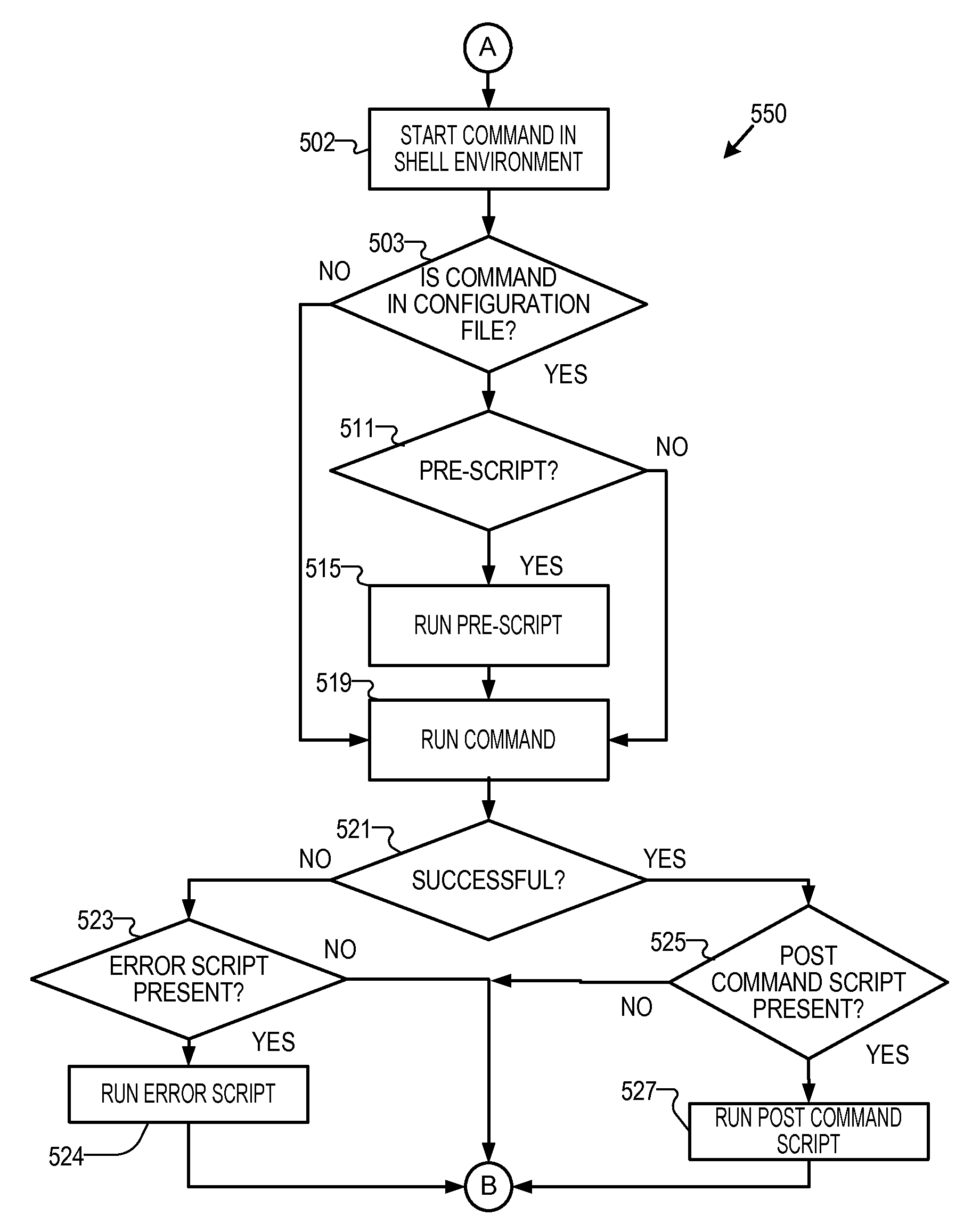
[0006]According to one embodiment, a method for avoiding loss of debug log data for configured commands during the operation of an operating system. A shell debug application executes a command shell script, by a computer, to control an amount of code path debug data is captured in memory buffers and saved. The shell debug application obtains, by the computer, a configuration file that includes at least one command. The shell debug application runs the command shell script in the command shell in response to detection of at least one script associated with the at least one command in the configuration file.

Problems solved by technology

A consequence of system installs, upgrades, and software refinement is that some configurations can be unstable.
As a result, an error can develop which may be identified by a customer.
An error is any detectable condition of a data processing system that operates below a user's expectations, below the manufacturer's expectations, or below nominal thresholds for which the data processing system is actually configured.
For example, an error can be a tract of data that fails to match a parity check.
An error can be a report made to a data processing system by a device outside of the data processing system, such as, for example, a 404 error response to a web-page query.
In many cases, an initial report that is stored to a log is merely a symptom of an error.
Rather than identify a person, device, or configuration that is a source or root cause, the initial report simply shows a degradation in data processing system performance.
When such symptoms are noticed, the lack of an elevated level of detail by affected commands and processes can limit the retrospective look at system history and confound analysis of the source of the error.

Method used


Image

  • Preventing log wrap with debug scripts
  • Preventing log wrap with debug scripts
  • Preventing log wrap with debug scripts

Examples


Embodiment Construction

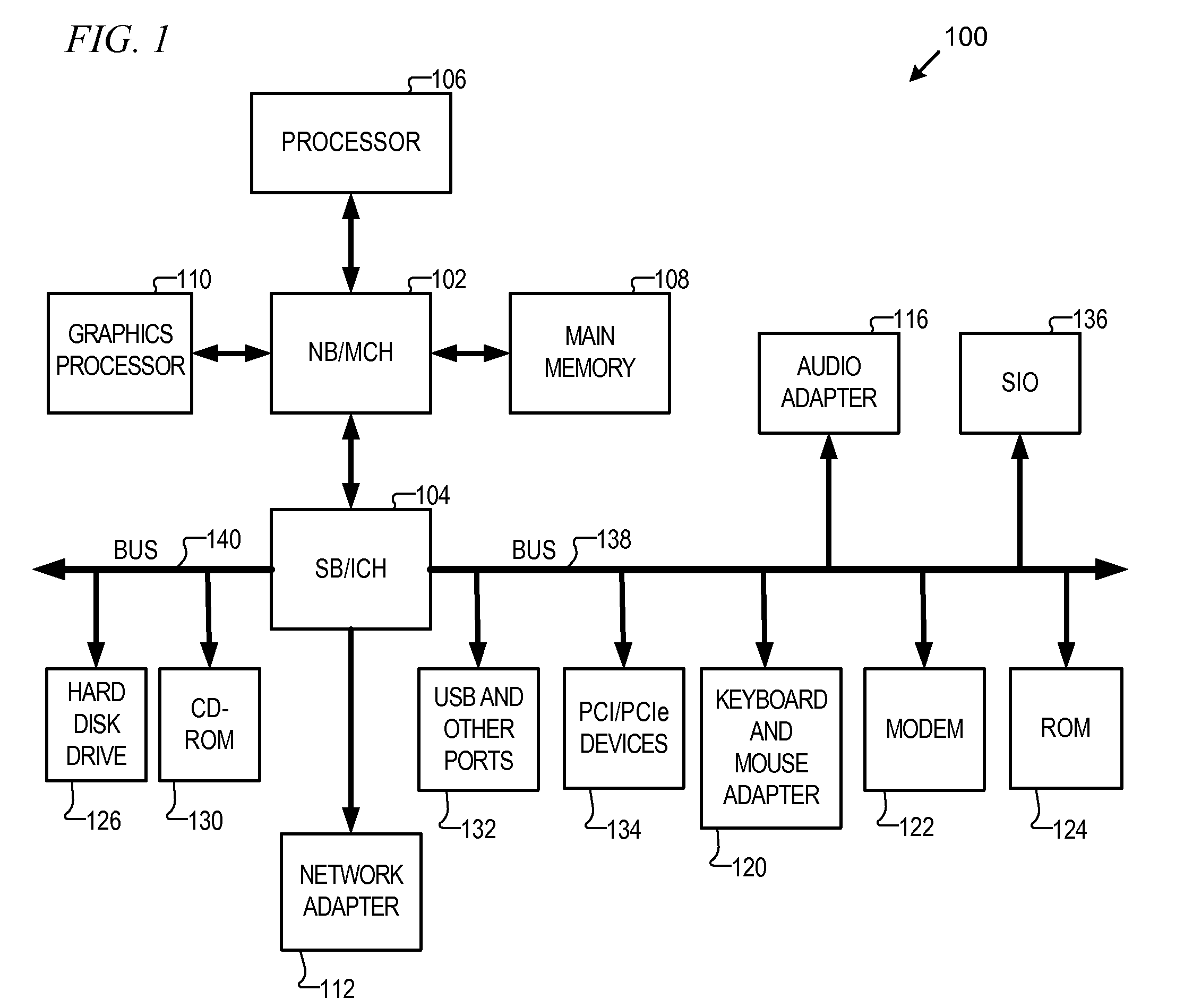
[0018]With reference now to the figures and in particular with reference to FIG. 1, a block diagram of a data processing system is shown in which aspects of an illustrative embodiment may be implemented. Data processing system 100 is an example of a computer, in which code or instructions implementing the processes of the present invention may be located. In the depicted example, data processing system 100 employs a hub architecture including a north bridge and memory controller hub (NB / MCH) 102 and a south bridge and input / output (I / O) controller hub (SB / ICH) 104. Processor 106, main memory 108, and graphics processor 110 connect to north bridge and memory controller hub 102. Graphics processor 110 may connect to the NB / MCH through an accelerated graphics port (AGP), for example.

[0019]In the depicted example, local area network (LAN) adapter 112 connects to south bridge and I / O controller hub 104 and audio adapter 116, keyboard and mouse adapter 120, modem 122, read only memory (RO...


PUM


Abstract

A shell debug application avoids loss of debug log data for configured commands during the operation of an operating system. A shell debug application executes a command shell script, by a computer, to control an amount of code path debug data captured in memory buffers and saved. The shell debug application obtains, by the computer, a configuration file that includes at least one command. The shell debug application runs the command shell script in the configuration file in response to detection of at least one script associated with the at least one command in the configuration file.

Description

TECHNICAL FIELD[0001]The present invention relates generally to a computer implemented method, data processing system, and computer program product for data processing system debugging. More specifically, the present invention relates to dynamically modifying logging details.DESCRIPTION OF THE RELATED ART[0002]Information technology staff of a manufacturer or system integrator provides support for data processing systems of varying configurations. Some data processing systems are grown by replacing parts as well as replacing subsystems as they become obsolete. A consequence of system installs, upgrades, and software refinement is that some configurations can be unstable. As a result, an error can develop which may be identified by a customer.[0003]Commands given on a data processing system can produce output in several forms. Typically, certain errors are expected and can be classified in advance with their status be written out to output. A log is the data structure to which errors...

Claims


Application Information

Patent Timeline
IPC IPC(8): G06F11/07G06F9/00
CPCG06F11/0787G06F11/0778
Inventor THOMPSON, ROBERT WRIGHT
Owner IBM CORP
Learn More