Cam Shaft/Cam Gear Assembly And Thrust Strategy For Engine Using Same

Active Publication Date: 2012-06-07
CATERPILLAR INC
View PDF1 Cites 11 Cited by
  • Summary
  • Abstract
  • Description
  • Claims
  • Application Information

AI Technical Summary

Problems solved by technology

While these and likely other thrust bearing strategies are known and available, they often suffer drawbacks associated with manufacturing complexity, cost, extra components, and even sometimes undesirable weakening of the camshaft in order to accommodate thrust bearing surfaces.
Because these lubrication galleries are sometimes arranged in parallel, and because the lubricating demands associated with different lubrication galleries may not be equal, it is possible that excess lubrication fluid may flow to and through one lubrication gallery leaving a deficit, and potentially less than adequate lubrication, for the components associated with a different lubrication gallery.
Finding strategies to insure that all of the lubrication galleries receive an adequate supply of lubricating oil can sometimes be problematic and elusive.

Method used


Image

  • Cam Shaft/Cam Gear Assembly And Thrust Strategy For Engine Using Same
  • Cam Shaft/Cam Gear Assembly And Thrust Strategy For Engine Using Same
  • Cam Shaft/Cam Gear Assembly And Thrust Strategy For Engine Using Same

Examples


Embodiment Construction

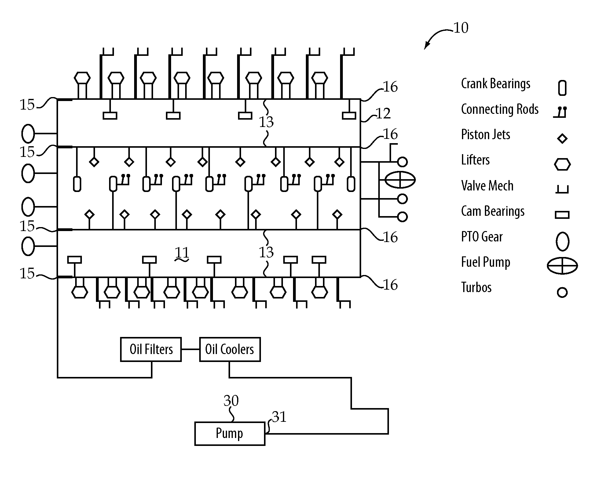
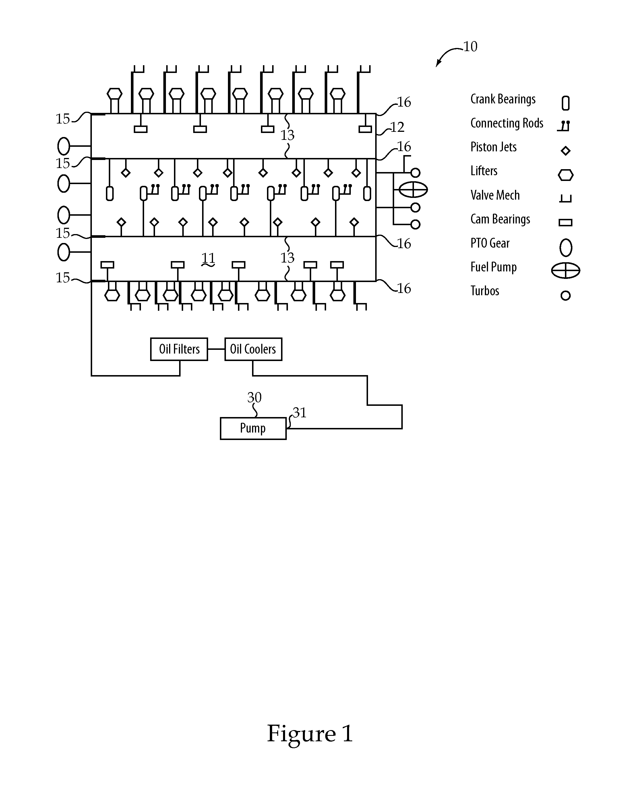
[0015]Referring to FIGS. 1 and 2, an engine 10 according to one aspect of the present disclosure may include a housing that defines a plurality of oil galleries 13. In the illustrated embodiment, four lubrication oil galleries 13 are arranged in parallel around a camshaft (see infra), and each include an inlet port 15 fluidly connected to receive lubrication oil pumped from an outlet 31 of a lubrication pump 30. Each of the lubrication galleries 13 also includes an opposite port 16 that open into, and are fluidly connected to one another via, a lubrication connection passage 12. Together, the lubrication galleries 13 provide lubricating oil to various moving components of engine 10 including crank bearings, connecting rods, piston jets, lifters and cam bearings as per the schematic of FIG. 1.

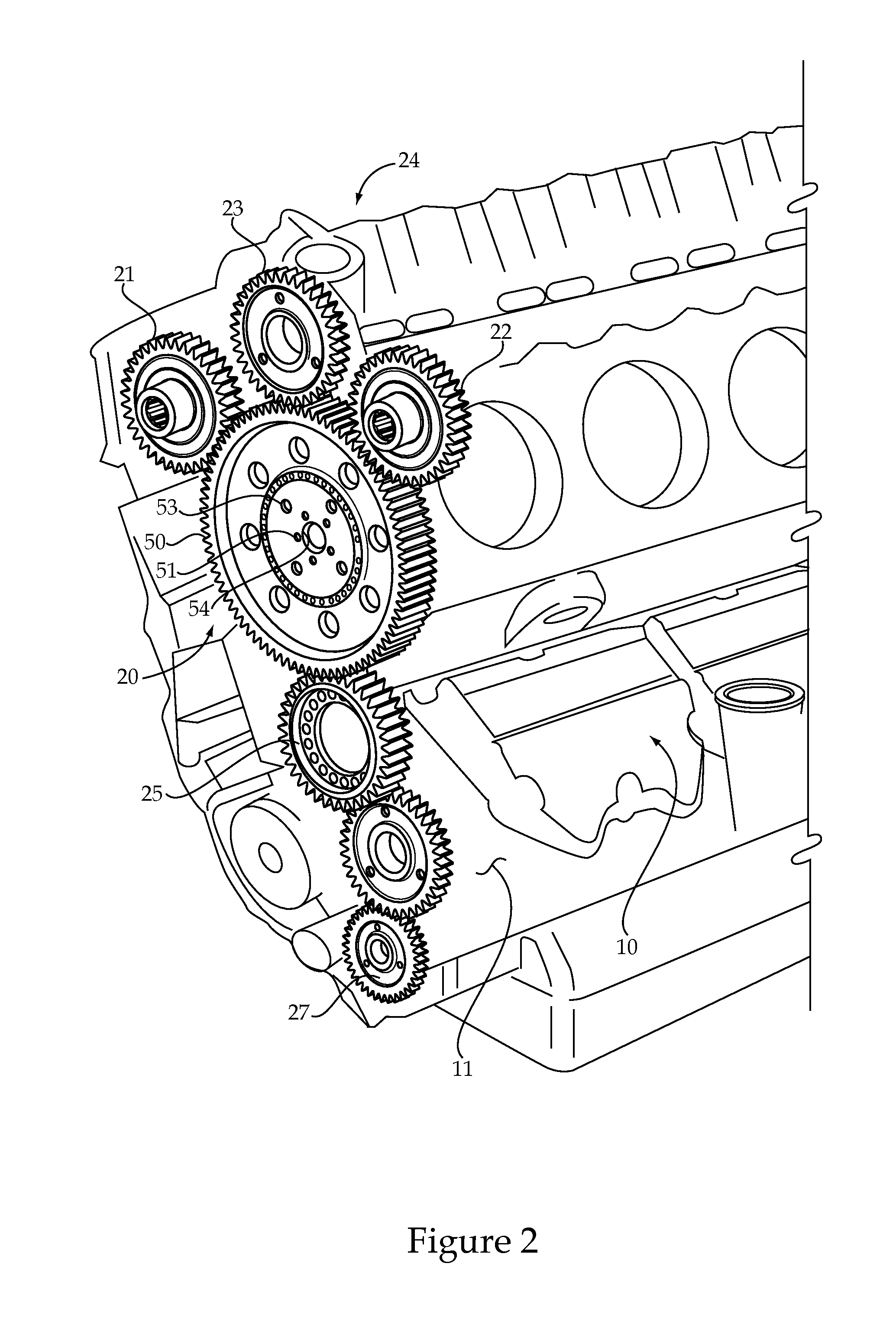
[0016]In another aspect, engine 10 may include a gear train 20 that includes a crank gear 25 meshed to drive rotation of a cam gear 50 as shown in FIG. 2. A majority of the power transmitted fro...


PUM


Abstract

An engine includes a camshaft supported in a housing for rotation about an axis of rotation. A cam gear is attached to one end of the camshaft and includes a first thrust bearing surface. A thrust ring is attached to the cam gear and includes a second thrust bearing surface. A thrust ring retainer is attached to the housing with a plurality of bolts and includes a pair of thrust surfaces trapped between the first thrust bearing surface of the cam gear and a second thrust bearing surface of the thrust ring. The thrust ring retainer also defines a portion of a lubrication connection passage that facilitates pressure equalization among a plurality of lubrication galleries arranged in parallel adjacent the camshaft.

Description

TECHNICAL FIELD[0001]The present disclosure relates generally to a thrust bearing strategy for a camshaft of an engine that is attached to a cam gear, and more particularly to maintaining a camshaft in an engine housing with thrust bearing surfaces on a cam gear and an attached thrust ring, respectively.BACKGROUND[0002]Most internal combustion engines utilize a rotating camshaft to open and close intake valves, exhaust valves, and sometimes actuate fuel injectors at precise timings for each of a plurality of engine cylinders. Most engines so equipped utilize one or more journal bearings to rotationally support the camshaft during rotation, and a pair of thrust bearing surfaces to limit movement of the camshaft along its axis of rotation. In some instances, such as that taught in U.S. Pat. No. 6,786,643, the camshaft includes an integrally formed disc that is trapped within a slot defined by the engine housing to prevent the camshaft from moving beyond where the disc contacts the sid...

Claims


Application Information

Patent Timeline
IPC IPC(8): F02F7/00F01M1/02
CPCF01L1/026F01L1/047F01L2001/0476F01L2001/054F16N27/00F01M9/105F01M11/02F02B67/04F16N25/00F01L2810/02
Inventor PETRY-JOHNSON, TRAVIS THOMASMILLWARD, PHILIP CHRISTOPHERHEINBUCH, RYAN MICHAELCHITTENDEN, JONATHAN
Owner CATERPILLAR INC
Why Eureka
Try Eureka