Solar cell

a solar cell and crystalline silicon technology, applied in the field of solar cells, can solve the problems of short lifetime of solar cells, low conversion efficiency, and increased cost of crystalline silicon solar cells, and achieve the effect of minimizing the loss of a light incident area

Active Publication Date: 2012-06-07
SHANGRAO JINKO SOLAR TECH DEV CO LTD
View PDF5 Cites 55 Cited by
  • Summary
  • Abstract
  • Description
  • Claims
  • Application Information

AI Technical Summary

Benefits of technology

[0007]Embodiments of the present invention are directed to a solar cell including a front electrode pattern that is able to minimize a loss of a light incident area.

Problems solved by technology

The cost of the crystalline silicon solar cell has increased due to a short supply of a silicon raw material and a shortage of a silicon substrate induced by installing a large number of solar cell systems in recent years.
Despite the low cost, however, low conversion efficiency and short lifetime of the solar cells, such as the thin-film silicon solar cell, the dye-sensitized solar cell, and the plastic solar cell, are blocking the industrialization thereof.

Method used


Image

  • Solar cell
  • Solar cell
  • Solar cell

Examples


Embodiment Construction

[0016]In the following description, it will be understood that when a layer or film is referred to as being “on” another layer or substrate, it can be directly on the other layer or substrate, or intervening layers may also be present. Further, it will be understood that when a layer is referred to as being “under” another layer, it can be directly under the other layer, and one or more intervening layers may also be present. In the figures, the dimensions of layers and regions are exaggerated or schematically illustrated, or some layers are omitted for clarity of illustration. In addition, the dimension of each part as drawn may not reflect an actual size.

[0017]Hereinafter, embodiments of the invention will be described with reference to the accompanying drawings.

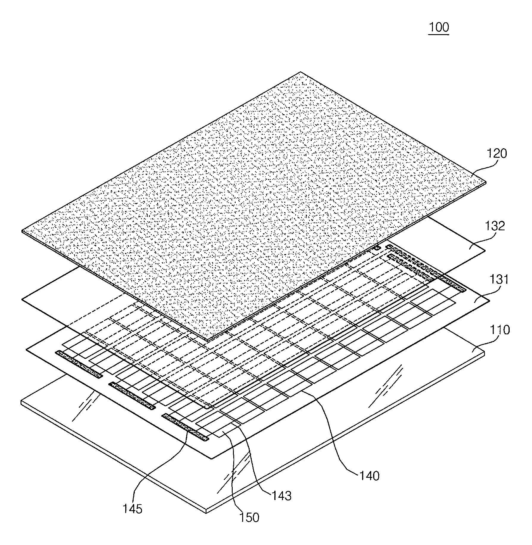
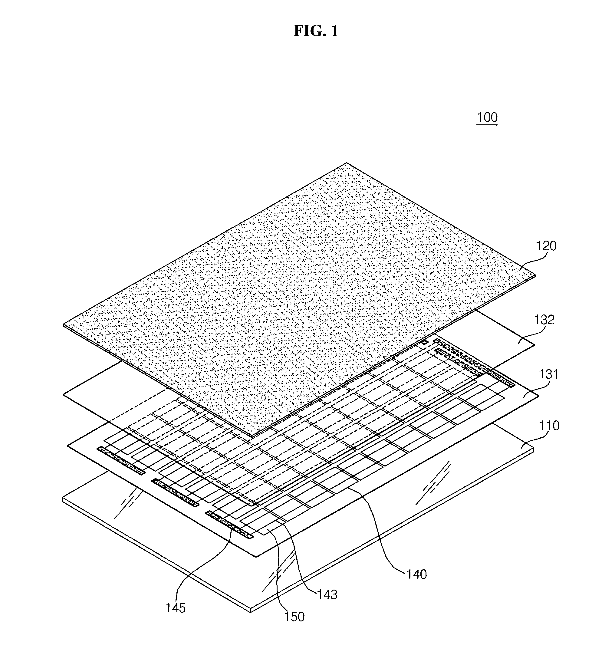
[0018]FIG. 1 is an exploded perspective view of a solar cell according to an embodiment of the invention, and FIG. 2 is a schematic cross-sectional view of the solar cell shown in FIG. 1.

[0019]Referring to FIGS. 1 and 2, a...


PUM


Abstract

A solar cell includes a photoelectric conversion layer and a front electrode on the photoelectric conversion layer. The front electrode includes a bus bar electrode; at least one first finger electrode directly connected to the bus bar electrode; a plurality of connecting electrodes extending from the bus bar electrode and having a width smaller than a width of the bus bar electrode, wherein the plurality of connecting electrodes includes portions that are spaced apart from each other to form a space therebetween; at least one second finger electrode connected to at least one of the plurality of connecting electrodes; and an auxiliary electrode formed at the space between the portions of the plurality of connecting electrodes.

Description

CROSS-REFERENCE TO RELATED APPLICATION[0001]This application claims priority to and the benefit of Korean Patent Application No. 10-2010-0123692, filed on Dec. 6, 2010 in the Korean Intellectual Property Office, the disclosure of which is incorporated herein by reference.BACKGROUND[0002]1. Field of the Invention[0003]Embodiments of the invention relate to a solar cell, and more particularly, to a solar cell having an improved electrode structure.[0004]2. Description of the Related Art[0005]Recently, as conventional energy resource such as petroleum and coal are expected to be exhausted and the environment is seriously polluted, significance of development in next-generation clean energy is increasing. Also, demand for renewable energy is increasing in the 21st century, and thus, interest in solar cells is also increasing. Solar cells do not pollute the environment, use a practically infinite energy resource, and can be used semi-permanently. Thus, solar cells are expected to be an e...

Claims


Application Information

Patent Timeline
Patent Type & Authority Applications(United States)
IPC IPC(8): H01L31/0224
CPCH01L31/022433Y02E10/547H01L31/1804Y02P70/50H01L31/02008H01L31/0201
Inventor KIM, SUNGJINKWON, TAEYOUNGLEE, SEONGEUNKWAG, GYEAYOUNG
Owner SHANGRAO JINKO SOLAR TECH DEV CO LTD
Why Eureka
Try Eureka