Intrusion detecting system

a detection system and intrusion detection technology, applied in the direction of burglar alarms, burglar alarm electric actuation, instruments, etc., can solve the problems of reducing the transmit radio wave output, reducing the maximum value of the monitor distance in the longitudinal direction of the cable, and unable to ensure the installation area. , to achieve the effect of suppressing false detection, reducing the space required to place the leakage coaxial transmission path, and enlarging the range of intrusion monitoring systems

Inactive Publication Date: 2012-06-07
MITSUBISHI ELECTRIC CORP
View PDF4 Cites 6 Cited by
  • Summary
  • Abstract
  • Description
  • Claims
  • Application Information

AI Technical Summary

Benefits of technology

[0007]The present invention has been made to solve the above problem, and aims at reducing a space required to place the leakage coaxial transmission path so as to suppress false detection, and enlarging a range where the intrusion monitoring system is available.

Problems solved by technology

This leads to such an adverse effect that an output of transmit radio waves must decrease, and a maximum value of the monitor distance in a longitudinal direction of the cables is shortened.
As a result, when the leakage coaxial transmission path is placed on an outer periphery of the existing site, there is a case in which a sufficient installation area cannot be ensured, and the leakage coaxial transmission path cannot be introduced.

Method used


Image

  • Intrusion detecting system
  • Intrusion detecting system
  • Intrusion detecting system

Examples


first embodiment

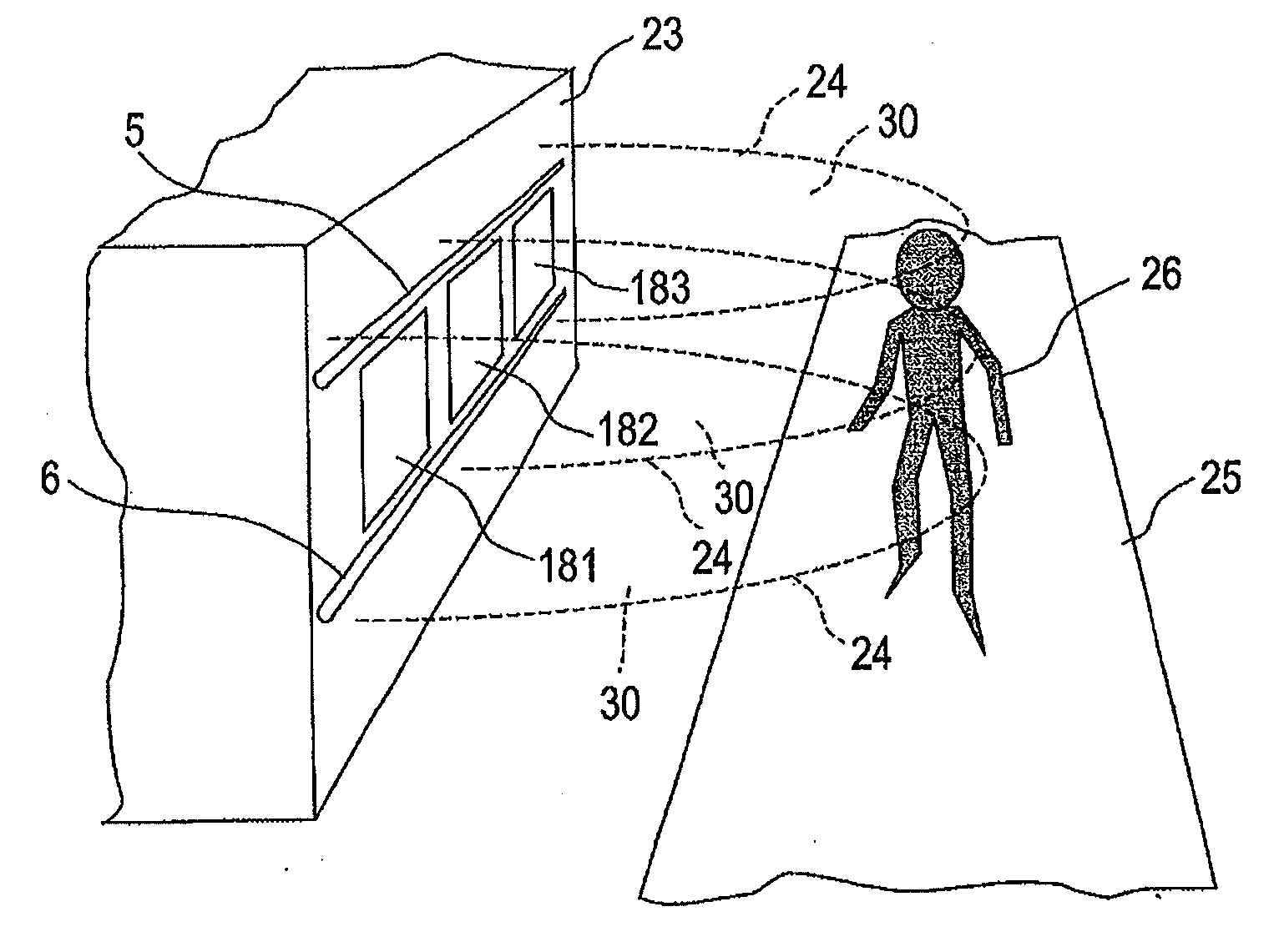
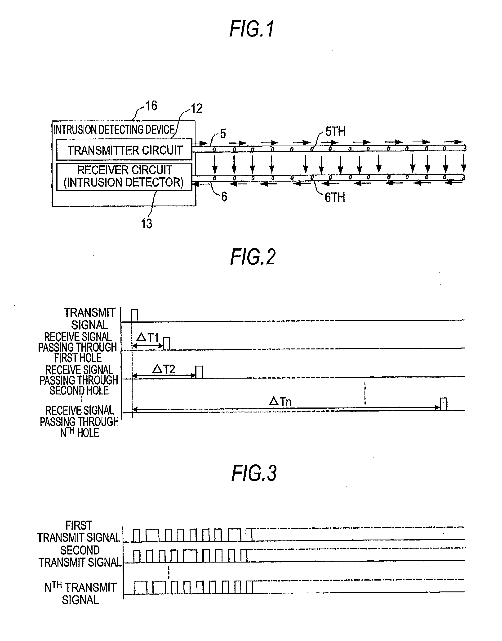
[0074]Hereinafter, a first embodiment of the present invention will be described with reference to FIGS. 1 to 5. FIG. 1 is a diagram illustrating a case of a rough configuration of an intrusion detecting system according to a first embodiment of the present invention. FIG. 2 is a diagram illustrating an example of a detection concept of an intrusion position according to the first embodiment of the present invention. FIG. 3 is a diagram illustrating a specific example of a transmit signal according to the first embodiment of the present invention. FIG. 4 is a block diagram illustrating an example of an internal configuration of an intrusion detecting device according to the first embodiment of the present invention. FIG. 5A is a diagram illustrating a conventional intrusion detecting system, FIG. 5B is a diagram illustrating a conventional intrusion detecting system of another simplification type, and FIG. 5C is a diagram illustrating an intrusion detecting system according to the f...

second embodiment

[0099]Hereinafter, a second embodiment will be described with reference to FIGS. 6A and 6B. An example of a specific intrusion detecting system targeting a plurality of windows in a building at the side of a passage in FIG. 6B is compared with the invention made in a process of reaching the present invention in FIG. 6A.

[0100]The leakage coaxial cable which is a representative case of the leakage transmission path is of two types of the radiation type and the surface wave type. In a standard configuration of the intrusion detecting system using the leakage coaxial transmission path, the leakage coaxial cable of the radiation type is used. In the leakage coaxial cables of the radiation type and the surface wave type, the radio wave radiation characteristics in a short-side direction of the cable are different from each other. The radio wave intensity in the case of using the radiation type is inversely proportional to a distance from the leakage coaxial cable. The radio wave intensity...

third embodiment

[0105]Hereinafter, a third embodiment of the present invention will be described with reference to FIG. 7.

[0106]As illustrated in FIG. 7, in the third embodiment of the present invention, both of the transmitter leakage transmission path 51 and the receiver leakage transmission path 61 are arranged inside the building 23.

[0107]Depending on the building, when the transmitter leakage transmission path 51 and the receiver leakage transmission path 61 are disposed outside the building 23 as illustrated in FIG. 6 described above, there is a possibility of interfering with the external appearance of the building. However, when both of the transmitter leakage transmission path 51 and the receiver leakage transmission path 61 are disposed inside the building 23 as illustrated in FIG. 7, the transmitter leakage transmission path 51 and the receiver leakage transmission path 61 do not interfere with the external building. Further, the transmitter leakage transmission path 51 and the receiver ...


PUM


Abstract

A space required to locate a leakage coaxial transmission path so as to suppress false detection is reduced, and a target range where the intrusion detecting system is available is enlarged. An intrusion detecting system in which a transmitter leakage transmission path that transmits a detection signal for detecting an intrusion and a receiver leakage transmission path that receives the detection signal leaked from the transmitter leakage transmission path are installed apart from each other within an intrusion monitor area, and an intrusion detecting device detects presence or absence of an intrusion object in the intrusion monitor area on the basis of a change in the detection signal received by the receiver leakage transmission path, wherein at least one of the transmitter leakage transmission path and the receiver leakage transmission path is a surface wave leakage coaxial transmission path.

Description

BACKGROUND OF THE INVENTION[0001]1. Technical Field[0002]The present invention relates to an intrusion detecting system that detects the presence or absence of an intrusion object such as a person and an intrusion position with the use of a leakage coaxial transmission path.[0003]2. Background Art[0004]In the intrusion detecting device using the leakage coaxial transmission path, with the use of a transmitter leakage coaxial cable and a receiver leakage coaxial cable, a signal is transmitted from the transmitter cable, and the presence or absence of the intrusion object and the intrusion position are determined according to a change in the signal received by the receiver cable.[0005]In a related-art wide-area intrusion detecting system using the leakage coaxial transmission path, the transmitter cable and the receiver cable are placed on or in the ground in parallel to each other in use (for example, refer to JP-A-2009-252020 (FIG. 7), JP-A-Hei-5(1993)-143877 (FIG. 1), JP-A-Hei-6(19...

Claims


Application Information

Patent Timeline
IPC IPC(8): G08B13/26
CPCG08B13/2497
Inventor FUJIWARA, JUNORITA, HIDEYUKI
Owner MITSUBISHI ELECTRIC CORP
Why Eureka
Try Eureka