Dc-dc converter and manufacturing method thereof

a technology of dc-dc converter and manufacturing method, which is applied in the direction of electric variable regulation, process and machine control, instruments, etc., can solve the problems of high input voltage, high voltage cannot be applied to the element using silicon material, and high input voltage, so as to reduce the number of manufacturing steps and reduce the manufacturing cost

Active Publication Date: 2012-06-07
SEMICON ENERGY LAB CO LTD
View PDF7 Cites 12 Cited by
  • Summary
  • Abstract
  • Description
  • Claims
  • Application Information

AI Technical Summary

Benefits of technology

[0012]Therefore, an element which decreases high input voltage is provided between an input terminal to which the high input voltage is applied and the control circuit. When the decreased voltage is supplied to the control circuit, there is no risk of breaking the control circuit.
[0030]In one embodiment of the disclosed invention, the number of manufacturing steps and manufacture cost can be decreased because a power device of a voltage converter circuit and a power device which decreases input voltage are formed in the same process.

Problems solved by technology

However, high voltage cannot be applied to the element using a silicon material because the element does not have high breakdown voltage.
Since silicon has a narrow band gap, an avalanche breakdown in which electrons are generated like an avalanche might occur.
However, although the high input voltage can drive the voltage converter circuit, the high input voltage might break the control circuit because it is too high as the voltage of the control circuit.
Accordingly, it is difficult to drive the DC-DC converter having a voltage converter circuit and a control circuit only by the single high input voltage.

Method used


Image

  • Dc-dc converter and manufacturing method thereof
  • Dc-dc converter and manufacturing method thereof
  • Dc-dc converter and manufacturing method thereof

Examples


Embodiment Construction

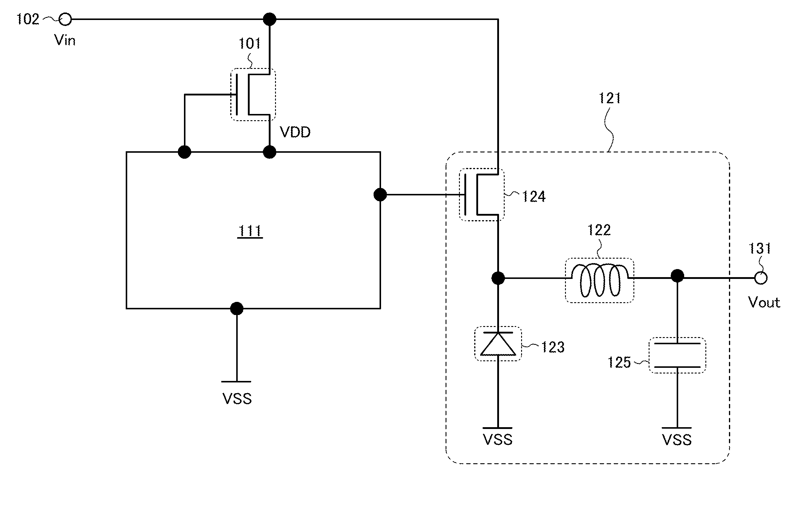
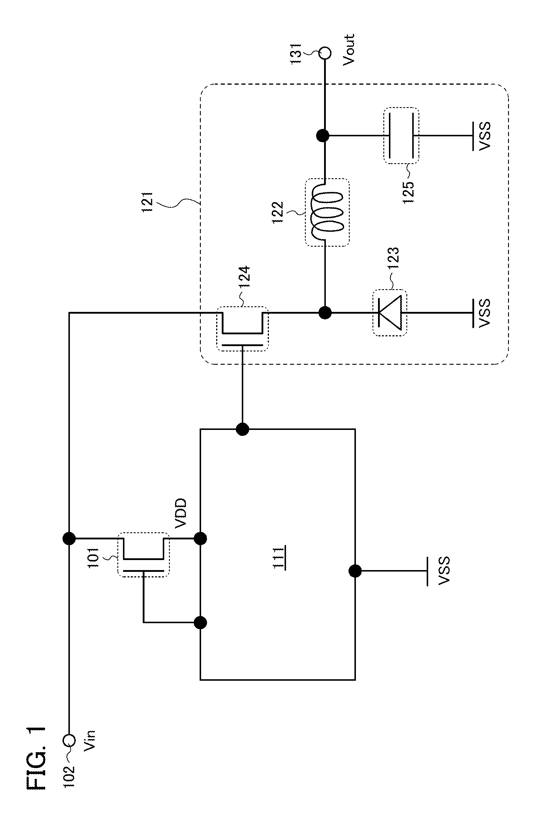
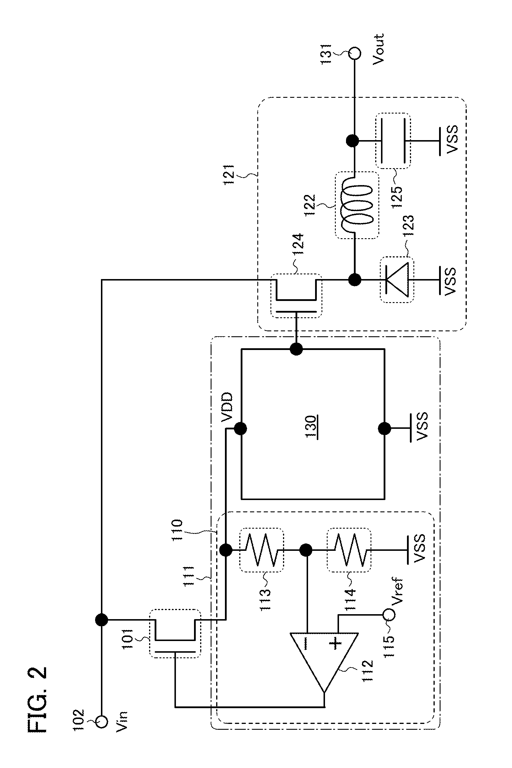
[0037]Embodiments of the invention disclosed in this specification will be hereinafter described with reference to the accompanying drawings. Note that the invention disclosed in this specification can be carried out in a variety of different modes, and it is easily understood by those skilled in the art that the modes and details of the invention disclosed in this specification can be changed in various ways without departing from the spirit and scope thereof. Therefore, the present invention is not construed as being limited to description of the embodiments. Note that, in the drawings hereinafter illustrated, the same portions or portions having similar functions are denoted by the same reference numerals, and repeated description thereof will be omitted.

[0038]Note that in the invention disclosed in this specification, a semiconductor device refers to an element or a device which functions by utilizing a semiconductor and includes, in its category, an electric device including an...


PUM


Abstract

A DC-DC converter is driven by single high input voltage, and includes a voltage converter circuit and a control circuit. The increase of the occupied area of the DC-DC converter is suppressed. The DC-DC converter includes an input terminal to which input voltage is applied; a voltage converter circuit connected to the input terminal, and including a first transistor; a control circuit configured to control the voltage converter circuit, and including a second transistor including a silicon material in a channel formation region; and a third transistor provided between the input terminal and the control circuit, and configured to convert the input voltage into power supply voltage that is lower than the input voltage. The first transistor and the third transistor include an oxide semiconductor material in channel formation regions. The first transistor and the third transistor are stacked over the second transistor with an insulating film provided therebetween.

Description

BACKGROUND OF THE INVENTION[0001]1. Field of the Invention[0002]One embodiment of the disclosed invention relates to a DC-DC converter and a manufacturing method thereof.[0003]2. Description of the Related Art[0004]In recent years, DC-DC converters have been widely used in order to drive circuits which are driven by DC voltage that is different from input voltage because devices which need DC voltage sources have been diversified (see Patent Document 1, Patent Document 2, and Patent Document 3).[Reference][0005][Patent Document 1] Japanese Published Patent Application No. 2009-148129[0006][Patent Document 2] Japanese Published Patent Application No. 2003-235251[0007][Patent Document 3] Japanese Published Patent Application No. 2009-254110SUMMARY OF THE INVENTION[0008]A DC-DC converter includes a voltage converter circuit and a control circuit which controls the voltage converter circuit. A power device which has high breakdown voltage is used for an element of the voltage converter ...

Claims


Application Information

Patent Timeline
Patent Type & Authority Applications(United States)
IPC IPC(8): H02M3/335H01L21/8234G05F3/08H02M1/00
CPCH01L27/1225H01L27/1251H02M2001/0006H02M3/33523H02M3/158H02M1/0006H01L27/027H01L27/105H01L29/517
Inventor TAKAHASHI, KEIITO
Owner SEMICON ENERGY LAB CO LTD
Why Eureka
Try Eureka