
Ultrasound Image Performance Determination

Active Publication Date: 2012-06-07
SIEMENS MEDICAL SOLUTIONS USA INC
View PDF21 Cites 43 Cited by
  • Summary
  • Abstract
  • Description
  • Claims
  • Application Information

AI Technical Summary

Benefits of technology

[0006]Embodiments contemplate a wireless communication system, in which the data transferred from the ultrasound probe to a Main Unit via a high-speed wireless link may be prone to bit errors due to potentially poor wireless signal quality, among other causes. The wireless interface may be designed to provide robust operation over a typical operating range and environment. The wireless link quality may degrade if the range exceeds approximately 3 meters, or the like, or if obstructions exist in the signal path. The receive antennas on the Main Unit may be designed with some directionality, so the signal may drop off if the probe is located outside of a direct line-of-sight. It may be useful to inform the ultrasound system user of the potential for image quality degradation due to poor wireless signal quality.

Problems solved by technology

Embodiments contemplate that an ultrasound imaging system with a wired or a wireless ultrasound probe may experience reduced imaging performance, perhaps as a result of poor transmission signal quality.
Embodiments contemplate a wireless communication system, in which the data transferred from the ultrasound probe to a Main Unit via a high-speed wireless link may be prone to bit errors due to potentially poor wireless signal quality, among other causes.
The wireless link quality may degrade if the range exceeds approximately 3 meters, or the like, or if obstructions exist in the signal path.

Method used


Image

  • Ultrasound Image Performance Determination
  • Ultrasound Image Performance Determination
  • Ultrasound Image Performance Determination

Examples


Embodiment Construction

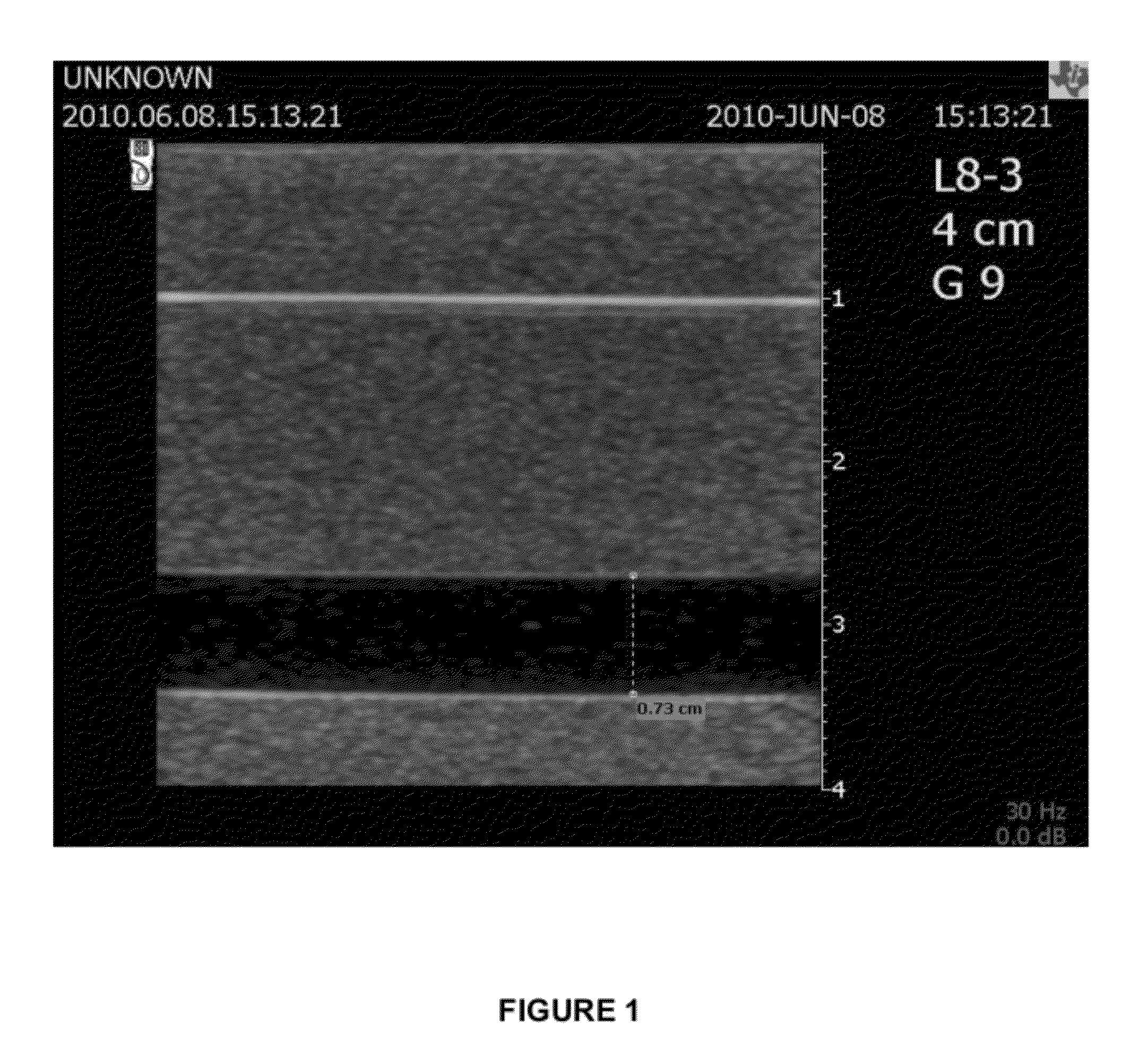
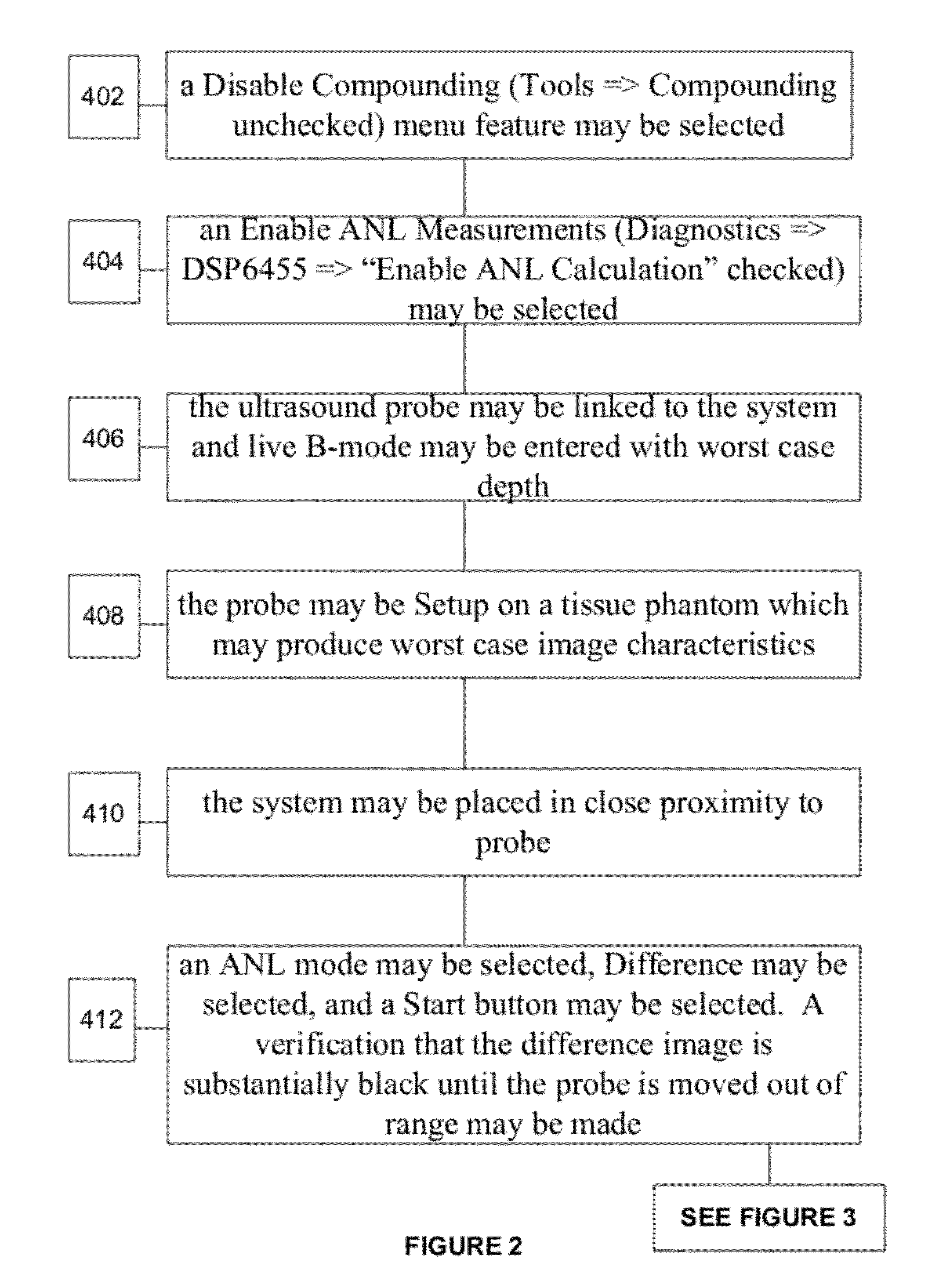
[0028]A detailed description of illustrative embodiments will now be described with reference to FIGS. 1-11. Although this description provides a detailed example of possible embodiments, it should be noted that the details are intended to be exemplary and in no way limit the scope of disclosed embodiments.

[0029]The subject matter of the described embodiments is described with specificity to meet statutory requirements. However, the description itself is not intended to limit the scope of this patent. Rather, the inventors have contemplated that the claimed subject matter might also be embodied in other ways, to include different steps or elements similar to the ones described in this document, in conjunction with other present or future technologies. Moreover, although the term “step” may be used herein to connote different aspects of methods employed, the term should not be interpreted as implying any particular order among or between various steps herein disclosed unless and exce...


PUM


Abstract

Embodiments contemplate methods and systems for determining an image performance measurement in an ultrasound system. Embodiments contemplate that data may be received from a remote unit of an ultrasound imaging system. One or more determinations of the measure of performance of an image may be made, where the image may be derivable from at least part of the data. The measure of image performance may be displayed on a main unit of the ultrasound imaging system.

Description

CROSS REFERENCE TO RELATED APPLICATIONS[0001]This application claims the benefit of U.S. Provisional Patent Application No. 61 / 390,727, filed on Oct. 7, 2010, and titled “Ultrasound Image Performance Determination”, the entire contents thereof being incorporated by reference herein, for all purposes.BACKGROUND[0002]In ultrasound systems, the ultrasound image that is displayed, typically on a main unit or base unit, represents an interpretation of ultrasound data gathered by an ultrasound probe. The ultrasound probe may transmit ultrasound waves into a medium and receive ultrasound waves echoed from elements of the medium. The echoed waves received by the ultrasound probe may be converted to digital or analog electrical signals, or data, that correspond to the received echoed ultrasound waves. The electrical signals (or data) may be processed, either in the ultrasound probe or in the main unit, or both, in order to produce the visual image used by the ultrasound technician to conduct...

Claims


Application Information

Patent Timeline
IPC IPC(8): G06K9/00
CPCG01S7/003G01S7/52073G01S7/5205
Inventor URBANO, JOSEPH A.RANDALL, KEVIN S.LANNUTTI, ANTHONY P.CANNON, MICHAEL G.KU, GEORGE C.
Owner SIEMENS MEDICAL SOLUTIONS USA INC
Learn More