Method and apparatus for improving the quality of a transmitted video signal

a video signal and transmission cable technology, applied in the field of video transmission, can solve the problems of inability to accurately convey the signal, affecting the loss of the transmission cable, so as to improve the quality of the transmitted signal, minimize the dc offset, and ensure the effect of transmission quality

Inactive Publication Date: 2009-03-05
RGB SYST INC
View PDF2 Cites 4 Cited by
  • Summary
  • Abstract
  • Description
  • Claims
  • Application Information

AI Technical Summary

Benefits of technology

[0013]In one or more embodiments of the present invention, a DC restore circuit is included in the transmitter, in the receiver, or both. In the transmitter, if the DC offset of the video source is unknown, the DC restore circuit centers the video signal received from the video

Problems solved by technology

Usually, a cable does not accurately convey the signal because of losses that accumulate along the cable path.
These losses, sometimes referred to as insertion losses, are primarily due to the physical characteristics of the transmission cable and sometimes due to imperfections in the cable construction.
A cable is a physical device and most physical devices exhibit some losses when a signal is conveyed through them.
Thus, longer length transmission cables typically exhibit more loss than shorter length cables.
Therefore, there exists a length limit for each transmission cable medium after which a transmitted video signal may no longer be acceptable.
However, coaxial cables are more expensive and difficult to install compared to twisted pair cables.
Historically, the significant insertion losses exhibited by twisted pair cables limited their use to transmission of low-resolution video (i.e., less than 10 MHz) signals.
Prior art video transmission systems can satisfactorily transmit analog video signals over twisted pair cable a distance of only approximately 300 feet because of the high insertion loss in the cable.
Such an arrangement results in significant cost and waste.
For example, the cost of the additional equipment may become prohi

Method used


Image

  • Method and apparatus for improving the quality of a transmitted video signal
  • Method and apparatus for improving the quality of a transmitted video signal
  • Method and apparatus for improving the quality of a transmitted video signal

Examples


Embodiment Construction

[0029]The invention comprises a method and apparatus for restoration of DC reference voltage levels in video signals transmitted over long distances using twisted pair conductors. In the following description, numerous specific details are set forth in order to provide a more thorough description of the present invention. It will be apparent, however, to one skilled in the art, that the present invention may be practiced without these specific details. In other instances, well-known features have not been described in detail so as not to obscure the invention.

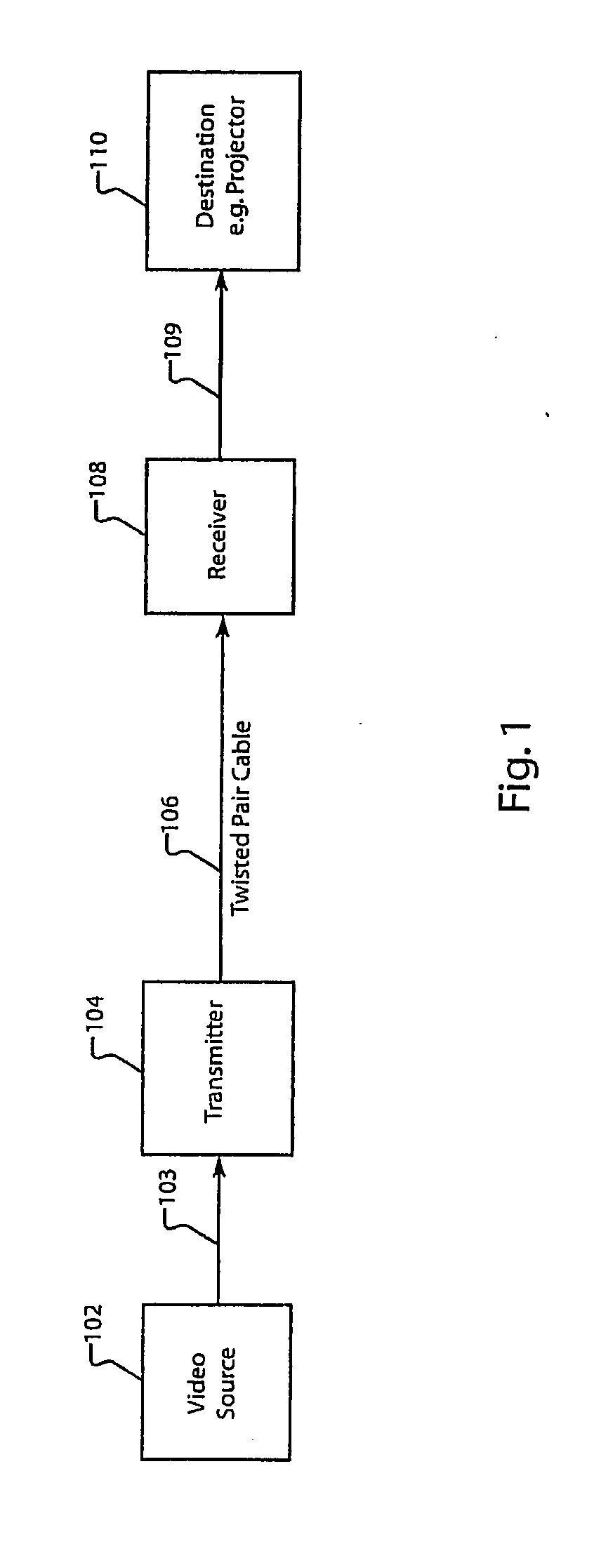
[0030]In one or more embodiments, the invention comprises a transmitter and a receiver tandem coupled together over a twisted pair cable for communication of video signals, including composite video, component video, S-Video, computer-video, and other high resolution video signals, over long distances. Embodiments of the present invention include one or more DC restore circuits to improve the quality of the transmitted video si...


PUM


Abstract

A feedback circuit for restoration of DC reference levels in video signals is presented. In one or more embodiments, a DC sample pulse is generated representing the back porch of an incoming video signal. A sample and hold circuit, which is controlled by the DC sample pulse, obtains the correct offset voltage in the output signal during this back porch period. The offset voltage feeds back through an integrating node in front of the circuit causing an amplifier to compensate for the signal offset thereby restoring the video signal to its proper DC voltage level with respect to ground.

Description

FIELD OF THE INVENTION[0001]This invention relates to the field of video transmission. More specifically the invention relates to a method and apparatus for improving the quality of a transmitted video signal by detecting DC reference levels in video signals incorporating tri-level and other synchronization signal formats.BACKGROUND[0002]Cables are used to convey electronic video signals from a source device to a destination device, e.g., a display device such as a display screen or video projector. Usually, a cable does not accurately convey the signal because of losses that accumulate along the cable path. These losses, sometimes referred to as insertion losses, are primarily due to the physical characteristics of the transmission cable and sometimes due to imperfections in the cable construction. A cable is a physical device and most physical devices exhibit some losses when a signal is conveyed through them. Thus, longer length transmission cables typically exhibit more loss tha...

Claims


Application Information

Patent Timeline
IPC IPC(8): H04B1/66
CPCH04N7/108
Inventor COLE, GARY DEAN
Owner RGB SYST INC
Why Eureka
Try Eureka