Single-trigger low-energy flip-flop circuit

a low-energy flip-flop circuit and single-trigger technology, applied in logic circuits, pulse generators, pulse techniques, etc., can solve the problems of large fraction of power dissipation in conventional digital integrated circuits consumed in the clock network reduce clock signal load, and reduce clock energy

Active Publication Date: 2013-05-07
NVIDIA CORP
View PDF11 Cites 3 Cited by
  • Summary
  • Abstract
  • Description
  • Claims
  • Application Information

AI Technical Summary

Benefits of technology

[0010]One advantage of the disclosed single-trigger low-energy flip-flop circuit is that the transistor device load on the clock signal is reduced to only three transistor gates. Therefore, the clock energy is reduced significantly compared with flip-flop circuits having greater loads on the clock signal. Additionally, the internal nodes are driven high or low during stable states of the circuit to produce a fully static design that does not rely on sizing relationships between the different transistors, such as transistors configured as sense amplifiers. Therefore, the single-trigger low-energy flip-flop circuit operation is robust, even when the characteristics of the transistors vary due to the fabrication process.

Problems solved by technology

Power dissipation is a significant problem in conventional integrated circuits.
A large fraction of the power dissipated in conventional digital integrated circuits is consumed in the clock network.

Method used


Image

  • Single-trigger low-energy flip-flop circuit
  • Single-trigger low-energy flip-flop circuit
  • Single-trigger low-energy flip-flop circuit

Examples


Embodiment Construction

[0018]In the following description, numerous specific details are set forth to provide a more thorough understanding of the present invention. However, it will be apparent to one of skill in the art that the present invention may be practiced without one or more of these specific details. In other instances, well-known features have not been described in order to avoid obscuring the present invention.

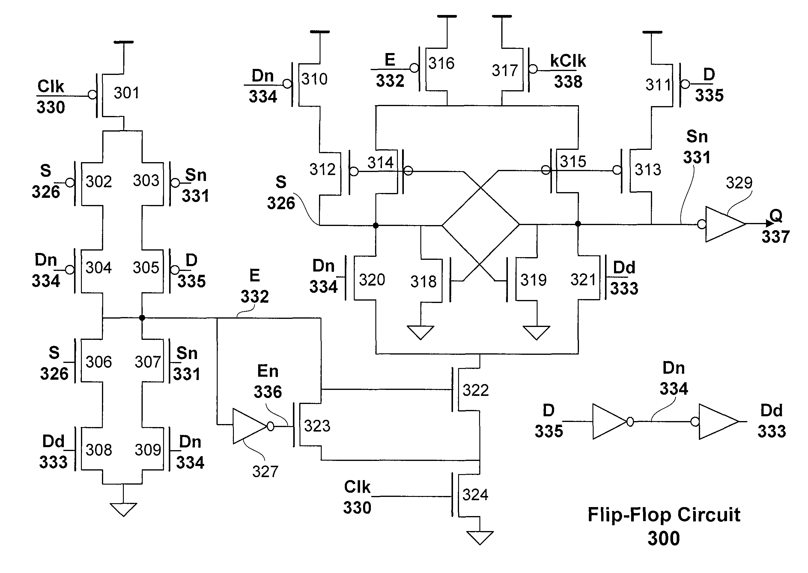
[0019]FIG. 3 illustrates a single-trigger low-energy flip-flop circuit 300, according to one embodiment of the invention. The flip-flop circuit 300 is a fully-static, clock-energy efficient flip-flop that presents only three loads to the clock and does not depend on transistor device size relationships. As shown in FIG. 3 transistors 306, 307, 308, 309, 318, 319, 320, 321, 322, 323, and 324 are NMOS devices and transistors 301, 302, 303, 304, 305, 310, 311, 312, 313, 314, 315, 316, and 317 are PMOS devices. The flip-flop circuit 300 includes four main sub-circuits, a single trigger sub-...


PUM


Abstract

One embodiment of the present invention sets forth a technique for capturing and storing a level of an input signal using a single-trigger low-energy flip-flop circuit that is fully-static and insensitive to fabrication process variations. The single-trigger low-energy flip-flop circuit presents only three transistor gate loads to the clock signal and none of the internal nodes toggle when the input signal remains constant. The output signal Q is set or reset at the rising clock edge using a single-trigger sub-circuit. A set or reset may be armed while the clock signal is low, and the set or reset is triggered at the rising edge of the clock.

Description

BACKGROUND OF THE INVENTION[0001]1. Field of the Invention[0002]The present invention generally relates to digital flip-flop circuits and more specifically to a single-trigger low-energy flip-flop circuit that is fully-static and insensitive to fabrication process variations.[0003]2. Description of the Related Art[0004]Power dissipation is a significant problem in conventional integrated circuits. A large fraction of the power dissipated in conventional digital integrated circuits is consumed in the clock network. The amount of energy that is consumed by flip-flops due to data transitions is small because the activity factor, the fraction of time the data input of the flip-flop toggles, is quite low, typically about 5-10%. In contrast, the clock input load and clock energy is an increasingly important metric to consider when determining the energy that is consumed by the latches and flip-flops in a conventional integrated circuit. Reducing the clock-switched capacitance by a given a...

Claims


Application Information

Patent Timeline
Patent Type & Authority Patents(United States)
IPC IPC(8): H03K3/00
CPCH03K3/012H03K3/286H03K3/356191H03K3/356139H03K3/037H03K3/356
Inventor ALBEN, JONAH M.DALLY, WILLIAM J.
Owner NVIDIA CORP
Why Eureka
Try Eureka