
Machine and method for producing and filling containers

a container and machine technology, applied in the direction of transportation and packaging, other domestic articles, packaging goods types, etc., can solve the problems of reduced performance or failure, reduced performance, and limited suitability of nozzles for nebulization or atomization of liquids, and achieves a robust mode of operation and high level of variability

Active Publication Date: 2016-09-08
KHS CORPOPLAST GMBH & CO KG
View PDF3 Cites 3 Cited by
  • Summary
  • Abstract
  • Description
  • Claims
  • Application Information

AI Technical Summary

Benefits of technology

The objective of this invention is to offer a new solution that is more reliable and flexible. This applies in particular to the creation of a new mode of operation that can be easily adapted to various needs and situations.

Problems solved by technology

Through atomization of the liquid, it is possible, depending on the droplet size, for moderate levels of cooling power to be achieved even with relatively small amounts of liquid, though said levels of cooling power may not be adequate for certain applications.
Such nozzles however exhibit only limited suitability for the nebulization or atomization of the liquid, because for this purpose, water must emerge at relatively high pressure from the nozzle and be atomized in the static air.
Here, there is the problem that the functionality of an arrangement of said type is highly dependent on the size of the nozzle opening, and pollution therefore leads very quickly to a reduction in performance or to failure.
Furthermore, such nozzles are limited in terms of their throughput and therefore exhibit only limited suitability for flush cooling or jet cooling.
With the known solutions, there is the problem in particular that a cooling path must be designed in advance, and can then be varied in terms of cooling power only to a very limited extent.

Method used


Image

  • Machine and method for producing and filling containers
  • Machine and method for producing and filling containers
  • Machine and method for producing and filling containers

Examples


Embodiment Construction

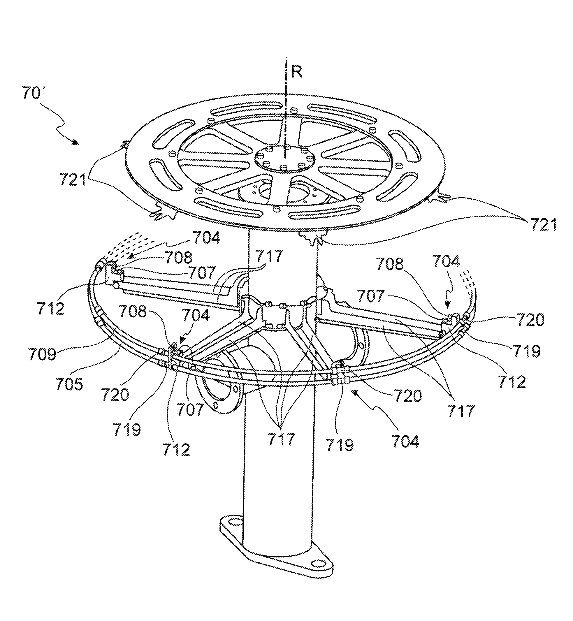
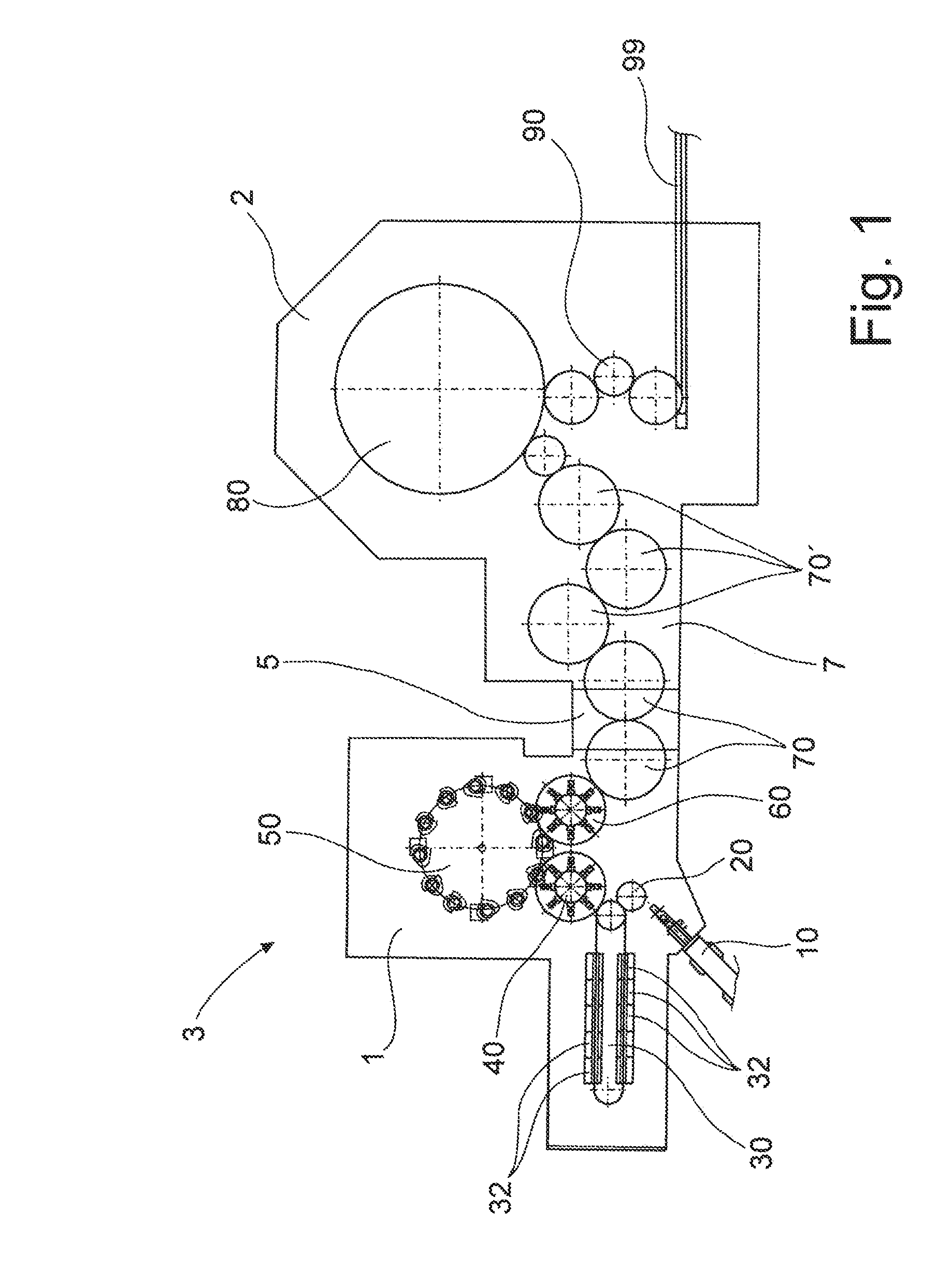
[0054]FIG. 1 schematically shows a machine 3 according to the invention for producing and filling containers. The machine 3 is in the form of a block machine, in which a stretch blow-molding machine 1 and a filling machine 2 are connected to one another by way of a transfer path 7 and are operated synchronously.

[0055]In the stretch blow-molding machine 1, it is firstly the case that containers are produced from in each case one parison. The generally injection-molded parisons are in this case composed primarily of a thermoplastic material, for example polyethylene terephthalate (PET), polypropylene (PP) or polyethylene naphthalate (PEN). It is basically also possible for biodegradable plastics, for example polylactides (PLA), to be used. Also known are parisons with additives or parisons with integrated intermediate layers, so-called multi-layer parisons, which may likewise be used in the context of the invention.

[0056]The stretch blow-molding machine 1 comprises a supply device 10 ...


PUM

PropertyMeasurementUnit
predefinable angleaaaaaaaaaa

Abstract

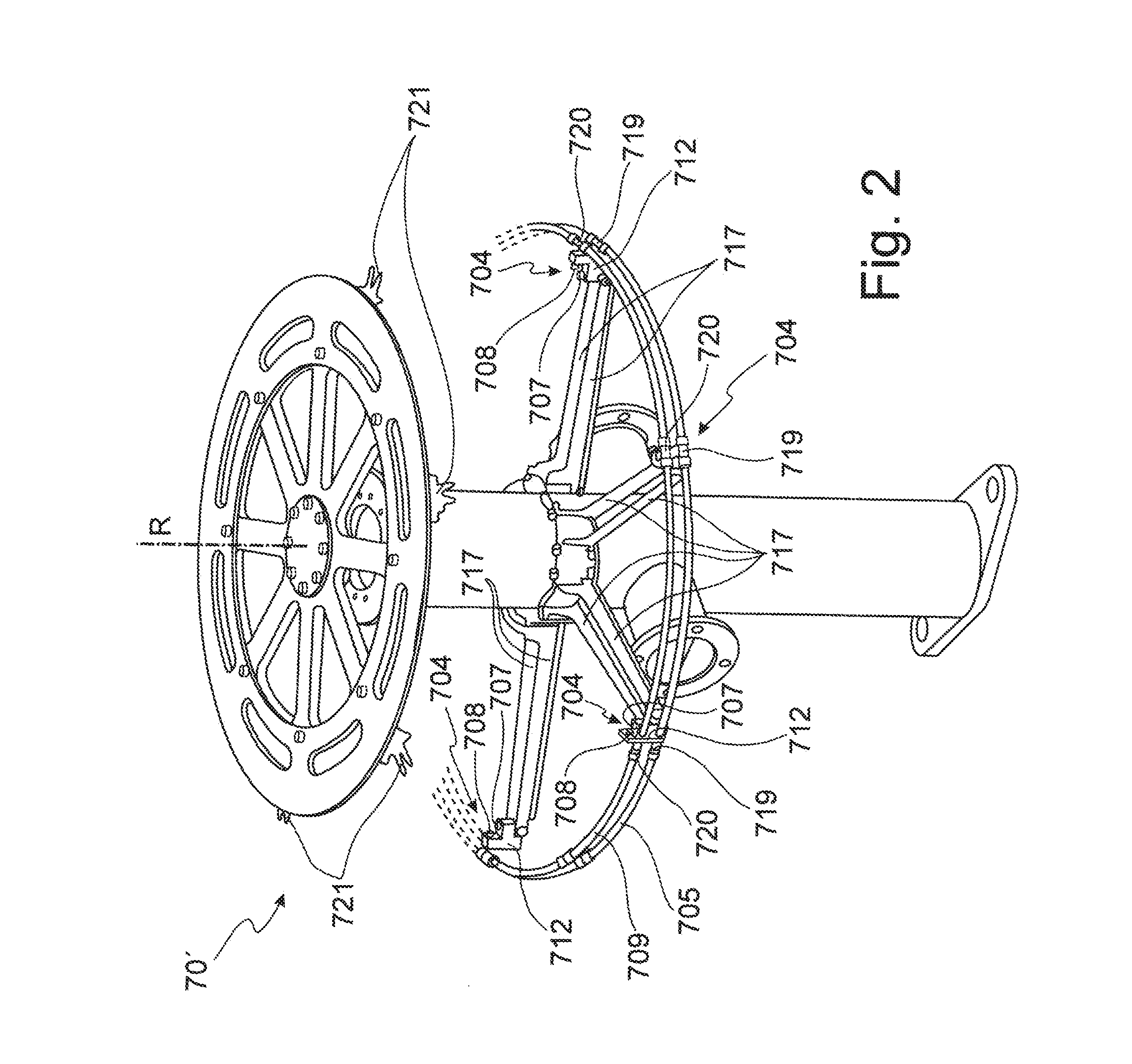
A machine for producing and filling containers, having: a heating device for thermal conditioning thermoplastic parisons; a blow-molding device for deforming the thermally conditioned parisons into containers by blow-molding or stretch blow-molding; a device for filling the containers with a product; and a transfer device for conveying the containers from the blow-molding device to the filling device. A nozzle arrangement is arranged in the region of the transfer device for impinging a cooling liquid on the containers. The nozzle arrangement has a gas nozzle connected by a gas line to a gas source. The nozzle arrangement has a liquid nozzle connected by a liquid line to a liquid source. The gas nozzle and the liquid nozzle are arranged and oriented relative to one another such that a liquid jet from the liquid nozzle strikes a gas jet from the gas nozzle in an intersection region.

Description

CROSS-REFERENCE TO RELATED APPLICATIONS[0001]The present application claims priority of DE 10 2015 002 795.6, filed Mar. 6, 2015, the priority of this application is hereby claimed and this application is incorporated herein by reference.BACKGROUND OF THE INVENTION[0002]The present invention relates to a machine for producing and filling containers, having at least one heating device for the thermal conditioning of parisons composed of a thermoplastic material, having at least one blow-molding device for the deformation of the thermally conditioned parisons to form in each case one container by way of a blow-molding process or a stretch blow-molding process, having at least one filling device for filling the containers with a product, and having a transfer device for conveying the containers from the blow-molding device to the filling device, wherein, in the region of the transfer device, there is arranged at least one nozzle arrangement for the impingement of a cooling liquid on th...

Claims


Application Information

Patent Timeline
Patent Type & Authority Applications(United States)
IPC IPC(8): B29C49/64B29C49/58B29C49/46
CPCB29C49/64B29C49/46B29C49/58B29C2049/4664B29C2049/5889B29C49/12B29C2949/78663B29C49/786B29C49/4205B29K2105/258B29K2101/12B29L2031/712B29C49/6418B29C49/42069B65B55/10B65B65/003B65B3/022B65B7/2835B29K2023/04B29K2023/12B29K2067/003B29K2067/046B29C49/08B29C49/78
Inventor HEROLD, THOMAS
Owner KHS CORPOPLAST GMBH & CO KG
Learn More