System and Method for Optical-Electrical-Optical Reach Extension in a Passive Optical Network

a passive optical network and optical-electrical technology, applied in the direction of electromagnetic transmission, electrical equipment, electromagnetic network arrangement, etc., can solve the problems of network operators facing optical signal losses

Inactive Publication Date: 2012-06-07
ALPHION
View PDF7 Cites 61 Cited by
  • Summary
  • Abstract
  • Description
  • Claims
  • Application Information

AI Technical Summary

Benefits of technology

[0007]According to one aspect, the present invention is direct to an optical network that may include an optical-electrical converter module within an OEO (Optical Electrical Optical) reach extension system (OEO RE system), the OEO RE system having an OEO port and including a

Problems solved by technology

However, the PON architecture, because of cost and fiber management reasons, has been implemented primarily using a point to multipoint architecture, with a single fiber being extended from a telecom central office facility to a split

Method used


Image

  • System and Method for Optical-Electrical-Optical Reach Extension in a Passive Optical Network
  • System and Method for Optical-Electrical-Optical Reach Extension in a Passive Optical Network
  • System and Method for Optical-Electrical-Optical Reach Extension in a Passive Optical Network

Examples


Embodiment Construction

[0023]In the following description, for purposes of explanation, specific numbers, materials and configurations are set forth in order to provide a thorough understanding of the invention. It will be apparent, however, to one having ordinary skill in the art that the invention may be practiced without these specific details. In some instances, well-known features may be omitted or simplified so as not to obscure the present invention. Furthermore, reference in the specification to phrases such as “one embodiment” or “an embodiment” means that a particular feature, structure or characteristic described in connection with the embodiment is included in at least one embodiment of the invention. The appearances of phrases such as “in one embodiment” or “in an embodiment” in various places in the specification do not necessarily all refer to the same embodiment.

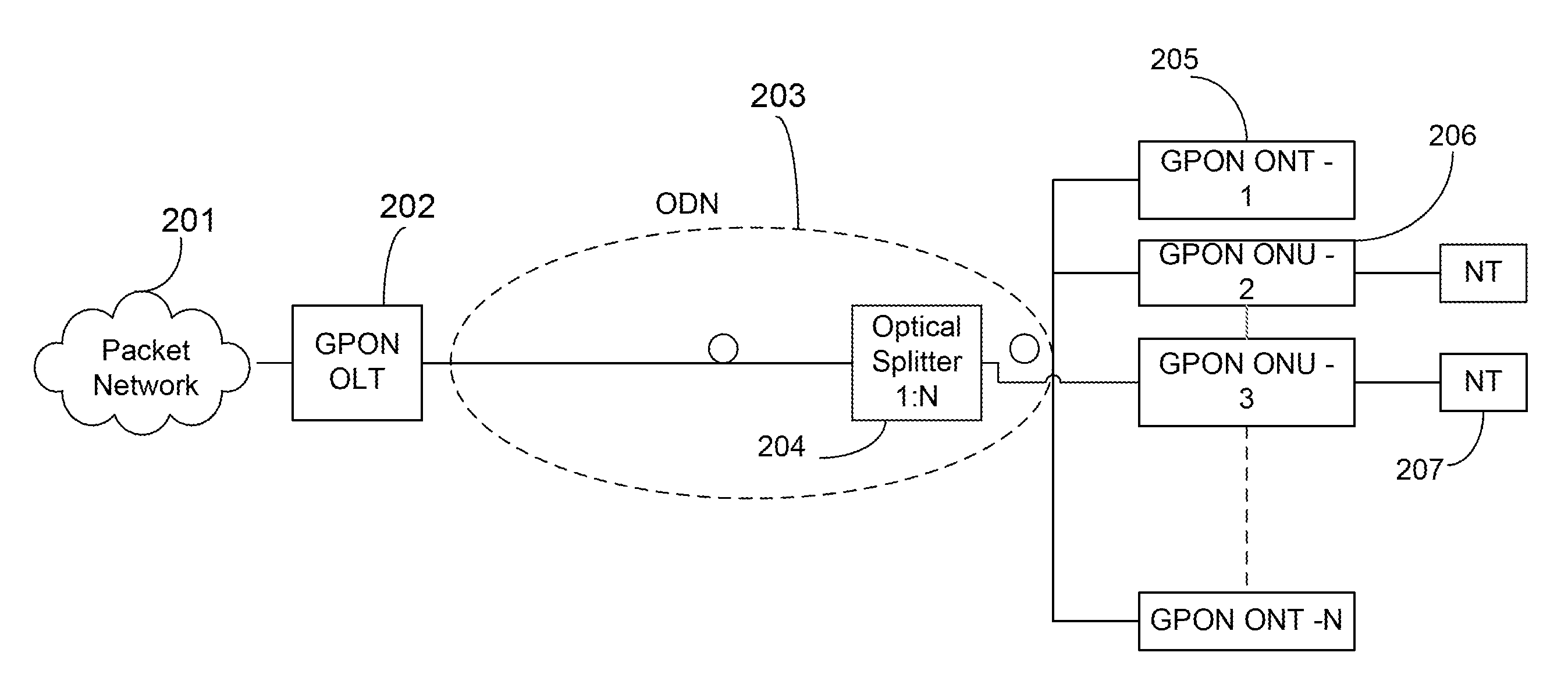
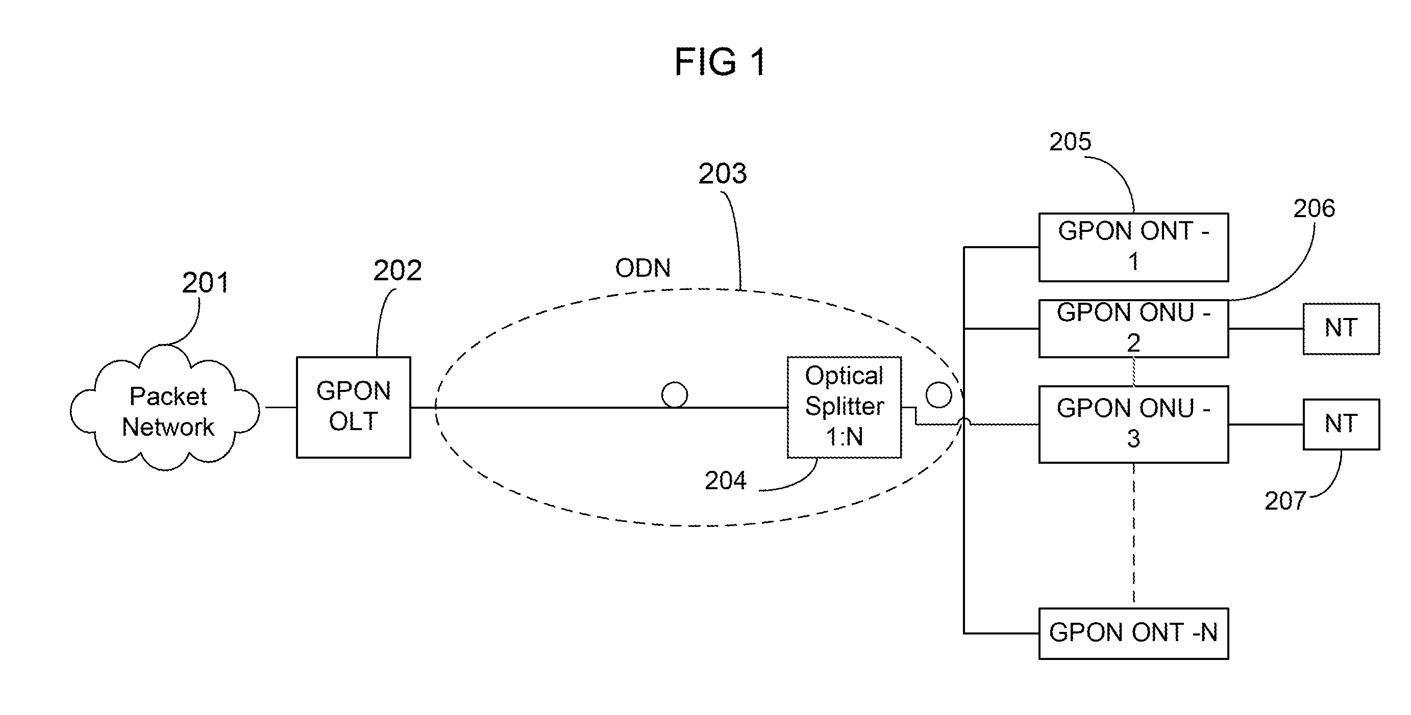
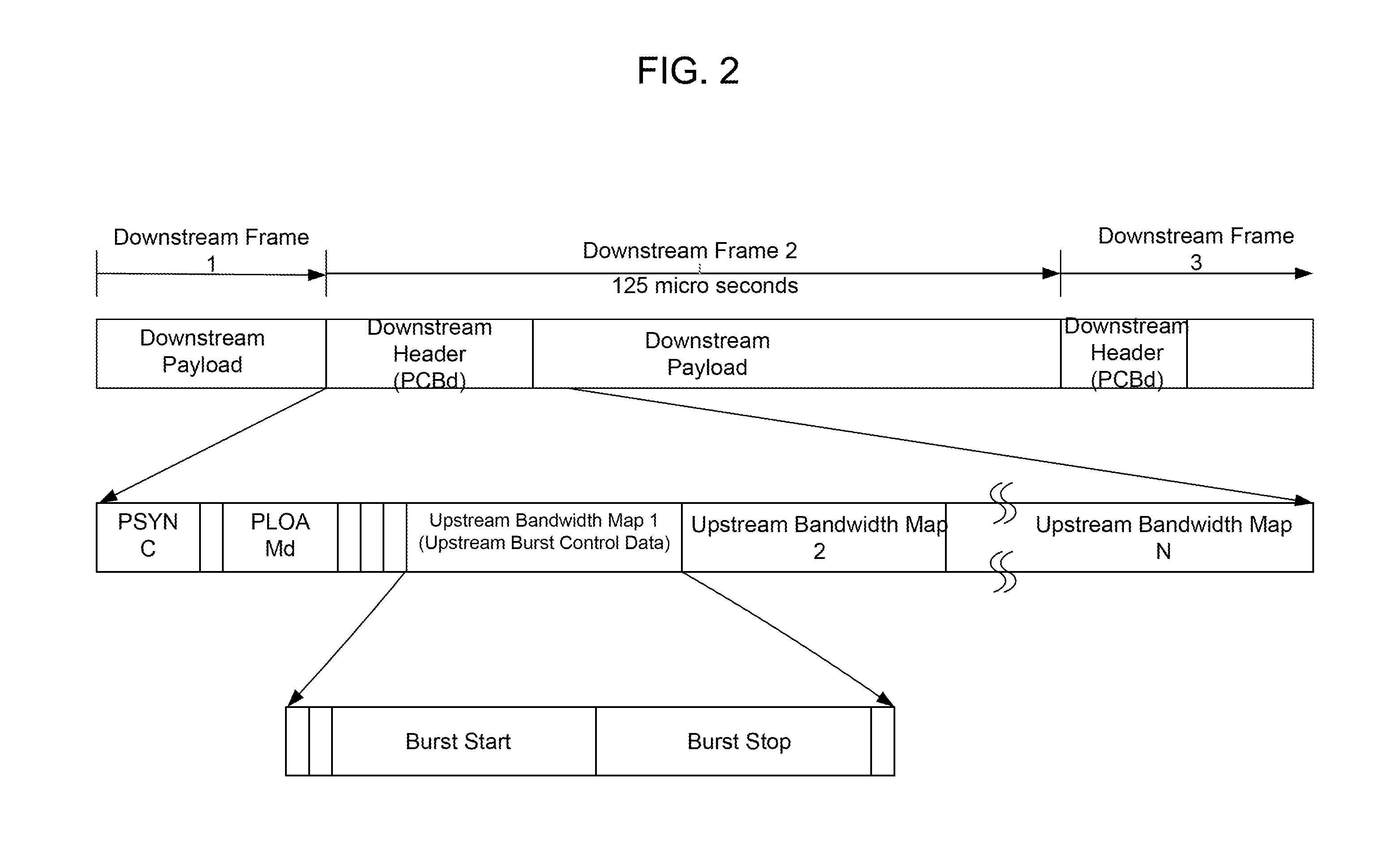
AcronymDescription3RReception, Recovery and Re-TimingBCDRBurst-Mode Clock and Data RecoveryCDRClock and Data RecoveryDSDownstream...


PUM


Abstract

A system and method are disclosed in which an optical network may include an optical-electrical converter module within an OEO (Optical Electrical Optical) reach extension system (OEO RE system), the OEO RE system having an OEO port and including a downstream frame regeneration block; and a downstream control data extraction block including a GPON operating parameter extraction module (GOPEM), wherein the GOPEM is operable to extract at least one OEO-port operating parameter from data frames arriving at the GOPEM module.

Description

CROSS-REFERENCE TO RELATED APPLICATIONS[0001]This application claims the benefit of U.S. Provisional Patent Application Ser. No. 61 / 374,428, filed Aug. 17, 2010, [Attorney Docket No. 312-45], entitled “System and Method for Optical-Electrical-Optical Reach Extension in a Passive Optical Network”, the entire disclosure of which application is hereby incorporated by reference herein.BACKGROUND OF THE INVENTION[0002]The ever-growing demand for high-speed broadband services has fueled interest in fiber-based access networks. Among the different architectures in which fiber-based access networks can be realized, the Passive Optical Network (PON) technology has become the architecture of choice for network operators due to the low cost, low maintenance, and high reliability of the passive network elements involved, and helps avoid the need for electrical power in order to operate.[0003]Passive, point-to-point fiber-based access networks can be implemented, such as the fiber-based point to...

Claims


Application Information

Patent Timeline
IPC IPC(8): H04B10/00
CPCH04B10/272H04Q11/0067H04Q2011/009H04Q2011/0088H04Q2011/0079
Inventor BAKHRU, UMESHGHAEMI, ALLANGRABBE, PAULKALA, ABHISHEKMEGEED, SHARIEFTHOGULUVA, JANARVARGHESE, MARTIN
Owner ALPHION
Why Eureka
Try Eureka