Hand drill

Inactive Publication Date: 2012-06-07
FUJI JUKOGYO KK
View PDF7 Cites 8 Cited by
  • Summary
  • Abstract
  • Description
  • Claims
  • Application Information

AI Technical Summary

Benefits of technology

[0017]With the present invention, the drill main body is fixed to the cylinder, so the drill main body displaces with the cylinder. The tip end portion of the piston rod is fixed to the base member, so when the contact surface of the base member is in contact with an object to be drilled, by pressing the drill toward the base member, the feeding speed of the drill blade can be controlled. Therefore, it is possible to suppress delamination that occurs when drilling holes in an object. When the damper is in

Problems solved by technology

However, because there are two guide rods attached to the hand drill, there is a problem that the entire device becomes large.
On the other hand, by using only one guide rod, it may be possible to make the overall device smaller, however, the contact plate and guide rod must be fastened at one po

Method used


Image

  • Hand drill
  • Hand drill
  • Hand drill

Examples


Embodiment Construction

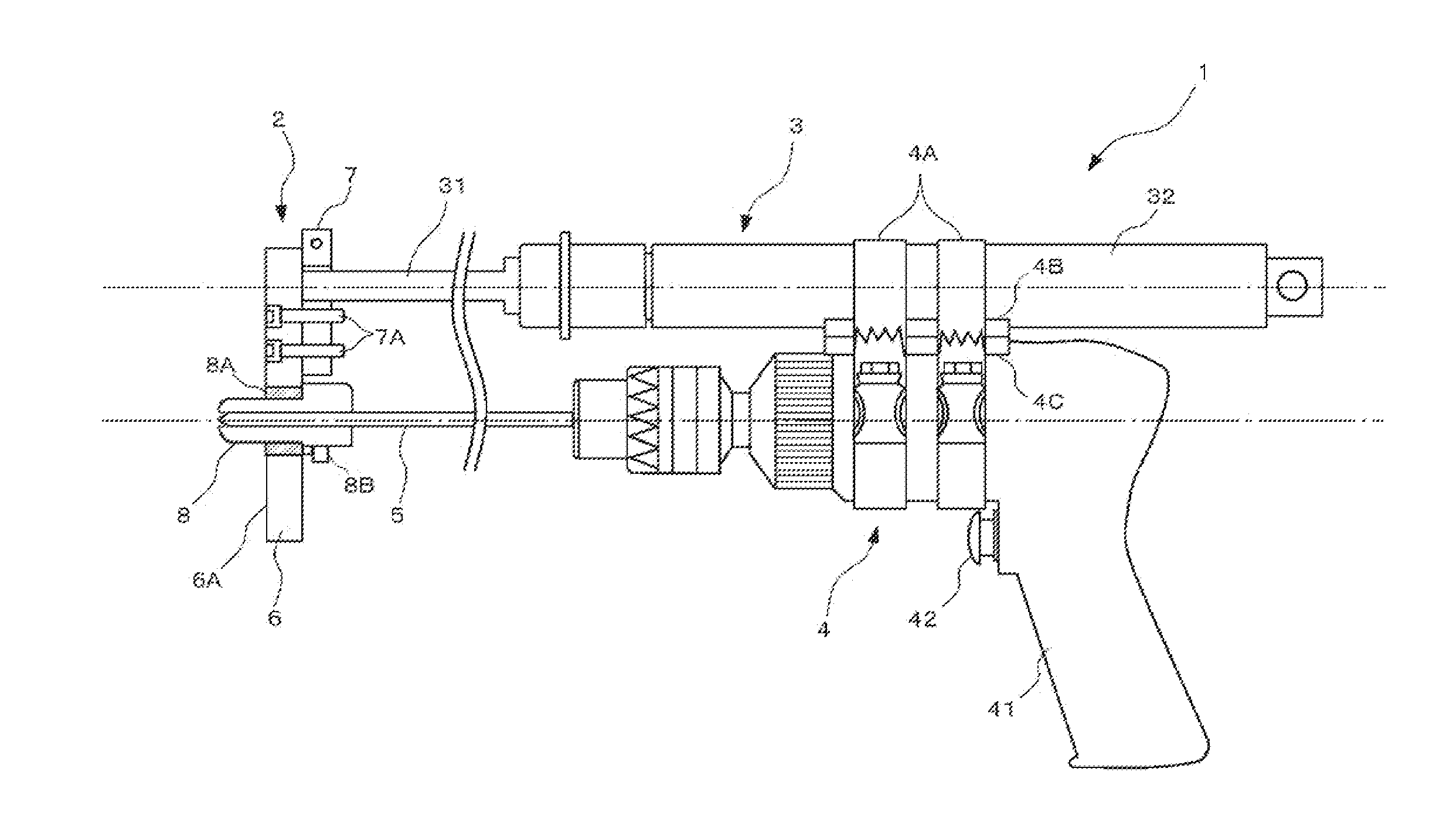
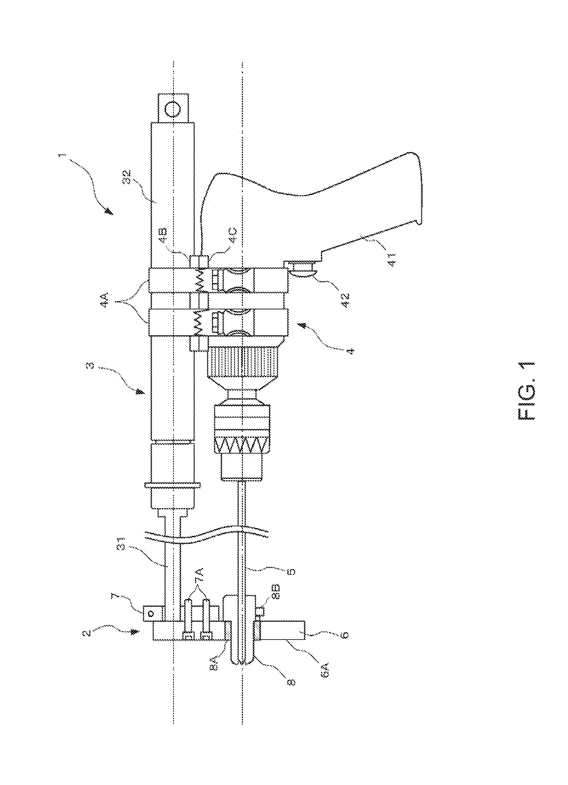
[0025]FIG. 1 is a schematic exterior view of a hand drill of an embodiment of the present invention. The hand drill 1 has a base member 2, a damper 3, a drill 4, and drill blade 5. In FIG. 1, the area around the base 2 (explained later) is illustrated as a cross section, and other parts are illustrated as an exterior view. The damper 3 comprises a piston rod 31 and a cylinder 32. The tip end of the piston rod 31 is fastened to the base member 2. The cylinder 32 houses the piston rod 31 inside and supports the piston rod 31 such that the piston rod can freely move in and out in the axial direction of the damper 3. In other words, the damper 3extends or contracts in its own axial direction, and functions as resistance to external force acting in the direction of extension or contraction. FIG. 1 is a drawing that illustrates the extended state of the damper 3. The same state is illustrated in the other drawings as well.

[0026]The drill 4 has a grip section 41 that is gripped in the hand...


PUM


Abstract

The object of the invention is to provide a hand drill that capable of suppressing delamination that occurs when drilling holes in an object, as well as being more compact. The hand drill has a base member, a damper, a drill and drill blade. The base member has a contact surface that comes in contact with an object being drilled, and a drill bushing. The damper comprises a piston rod and a cylinder, and extends or contracts in its own axial direction. The tip end section of the piston rod is fastened to the base member. The drill is fastened to the cylinder and displaces together with the cylinder. The drill blade is installed in the drill so that it is parallel to the axial direction of the damper. When the damper is in the extended state, the tip end of the drill blade is located at the tip end of the drill bushing.

Description

CROSS REFERENCE TO RELATED APPLICATIONS[0001]This application claims priority under 35 U.S.C. 119 based upon Japanese Patent Application Serial No. 2010-272829, filed on Dec. 7, 2010. The entire disclosures of the aforesaid applications are incorporated herein by reference.FIELD OF THE INVENTION[0002]The present invention relates to a hand drill, and more particularly to a hand drill having a damper for controlling the feeding speed of the drill blade.BACKGROUND OF THE INVENTION[0003]Japanese Laid-open Patent Publication No. 2008-149432 discloses a method of suppressing delamination, which occurs when drilling holes in an object, by providing a damper in each of two guide rods that are fixed to a hand drill in order to control the feeding speed of a drill blade. More specifically, the guide rods are formed such that they extend and contract along the feed direction of the drill blade, with the speed of expansion and contraction being controlled by the dampers. The tip of each guide ...

Claims


Application Information

Patent Timeline
IPC IPC(8): B23B45/14
CPCY10T408/564B23B49/02
Inventor SAITO, MANABUNAKAHATA, TATSUOTAKAHASHI, HIDEHARU
Owner FUJI JUKOGYO KK
Why Eureka
Try Eureka