Structure of electromagnetic wave resistant connector for flexible circuit cable
- Summary
- Abstract
- Description
- Claims
- Application Information
AI Technical Summary
Benefits of technology
Problems solved by technology
Method used
Image
Examples
first embodiment
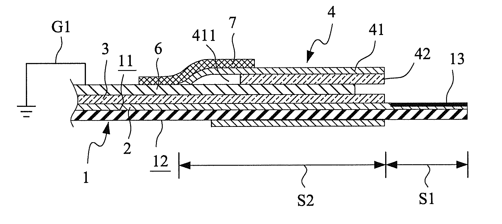
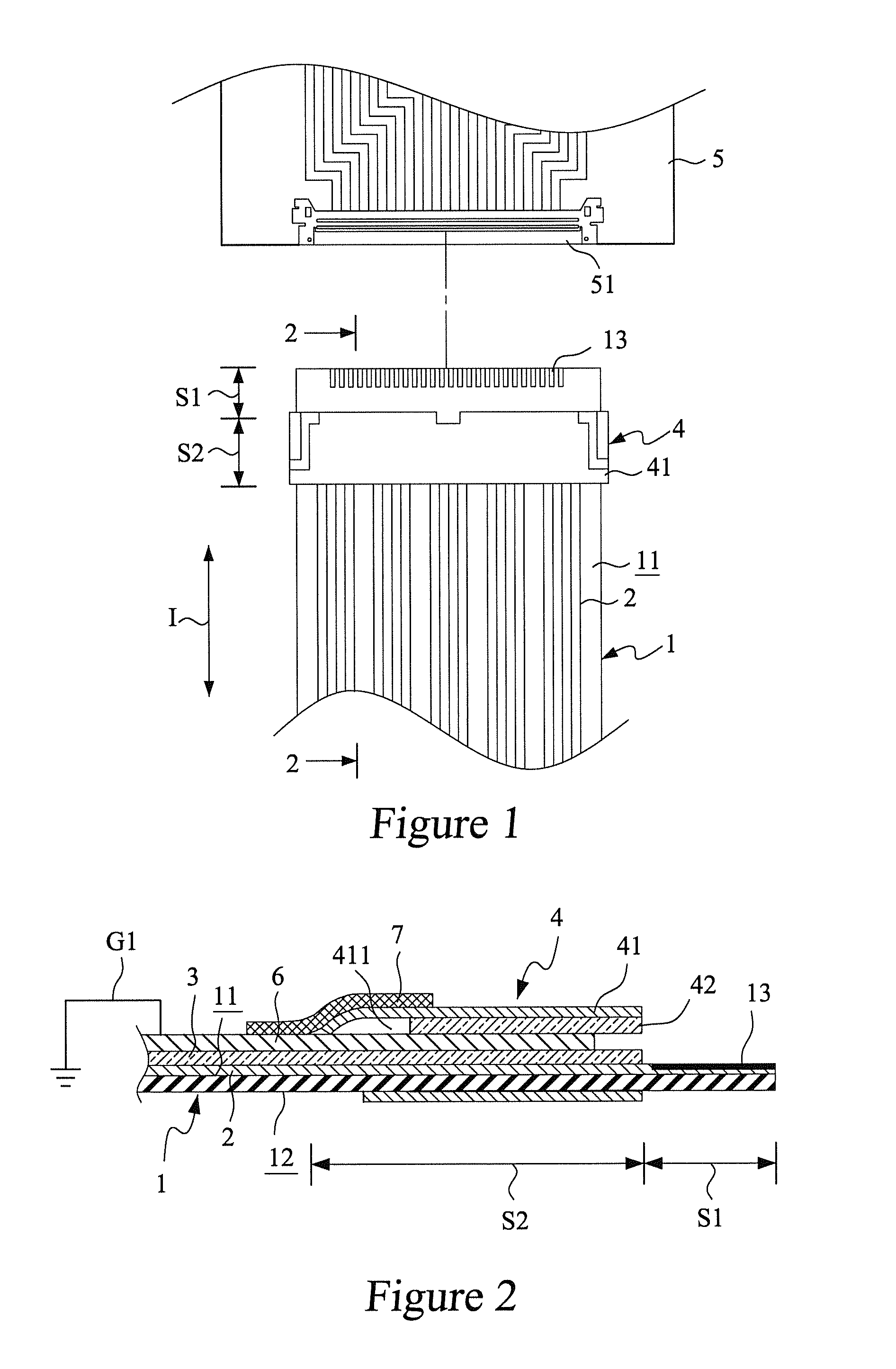
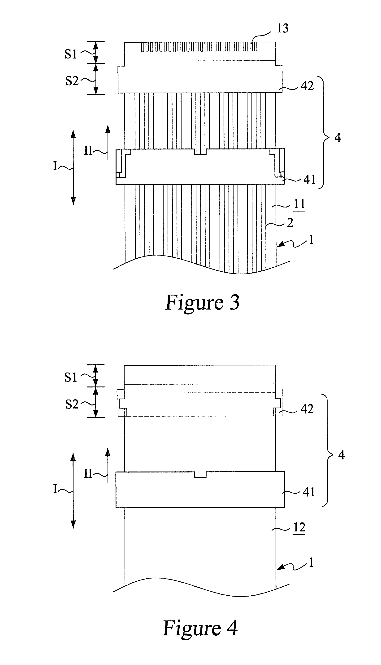
[0018]With reference to the drawings and in particular to FIGS. 1 and 2, which show a schematic view and a cross-sectional of a first embodiment according to the present invention, a flexible flat cable 1 has a first surface 11 and a second surface 12. The flexible flat cable 1 extends in a cable extension direction I so that the flexible flat cable 1 forms an insertion section S1 at a free end thereof and also forms an insertion device mounting section S2 in a section thereof adjacent to the insertion section S1.
[0019]The first surface 11 of the flexible flat cable 1 forms a plurality of parallel and spaced conductive traces 2. The conductive traces 2 extend through the insertion device mounting section S2 into the insertion section S1 of the flexible flat cable 1 to form a plurality of conductive contacts 13 in the insertion section S1.
[0020]An insulation layer 3 is provided on the first surface 11 of the flexible flat cable 1 and surfaces of the conductive traces 2. An insertion ...
second embodiment
[0025]Referring to FIG. 6, a cross-sectional view of a second embodiment according to the present invention is shown. In the instant embodiment, part / components that are similar or identical to counterparts of the previous embodiment bear the same reference for consistency and simplification. In the instant embodiment, a mechanical reinforcement layer 8 made of insulation material is provided on the second surface 12 of the flexible flat cable 1 to cover both the insertion section S1 and the insertion device mounting section S2. The mechanical reinforcement layer 8 helps improving the mechanical strengths of the insertion section S1 and the insertion device mounting section S2 of the flexible flat cable 1 to ensure stable insertion of the flexible flat cable 1 into the insertion slot 51 of the circuit board 5.
third embodiment
[0026]Referring to FIG. 7, a cross-sectional view of a third embodiment according to the present invention is shown. In the instant embodiment, a shielding layer 9 made of a conductive material is provided on the second surface 12 of the flexible flat cable 1 to cover both the insertion section S1 and the insertion device mounting section S2. The shielding layer 9 is in electrical engagement with the metal member 41 of the insertion device 4 and the shielding layer 9 is electrically connectable to a second grounding path G2. The second grounding path G2 and the first grounding path G1 may be connected to each other through a via or by a conductive material extending between both surfaces to thereby form a common ground.
PUM
 Abstract
Description
Claims
Application Information
 - R&D
- Intellectual Property
- Life Sciences
- Materials
- Tech Scout
- Unparalleled Data Quality
- Higher Quality Content
- 60% Fewer Hallucinations
Browse by: Latest US Patents, China's latest patents, Technical Efficacy Thesaurus, Application Domain, Technology Topic, Popular Technical Reports.
© 2025 PatSnap. All rights reserved.Legal|Privacy policy|Modern Slavery Act Transparency Statement|Sitemap|About US| Contact US: help@patsnap.com


