
Rolling bearing for tensioning roller device and associated tensioning roller

a technology of rolling bearing and tensioning roller, which is applied in the direction of bearing unit rigid support, bearing, mechanical equipment, etc., can solve the problems of thread burrs, thread burrs, and thread burrs on the sides of threads, and achieves good perpendicularity and is easy to manufacture and assemble. , the effect of good perpendicularity

Inactive Publication Date: 2012-06-07
AB SKF
View PDF8 Cites 20 Cited by
  • Summary
  • Abstract
  • Description
  • Claims
  • Application Information

AI Technical Summary

Benefits of technology

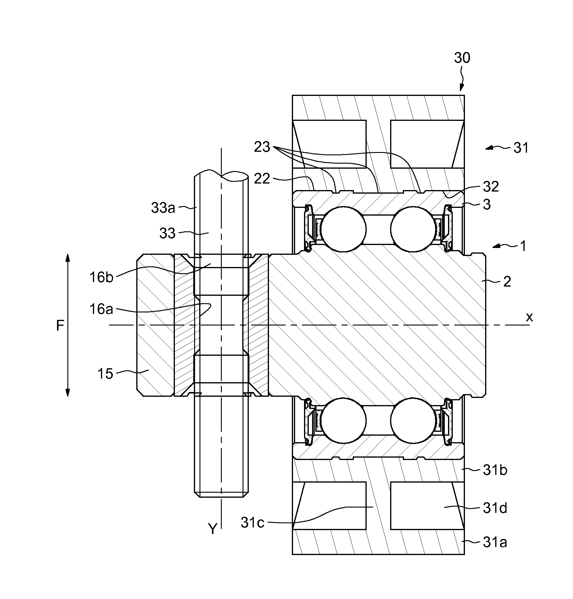
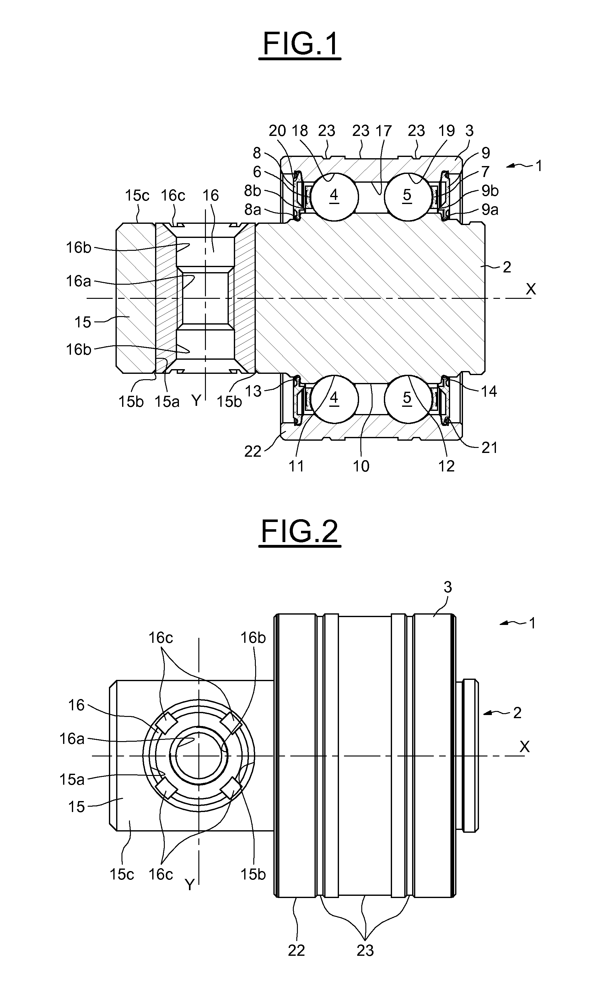
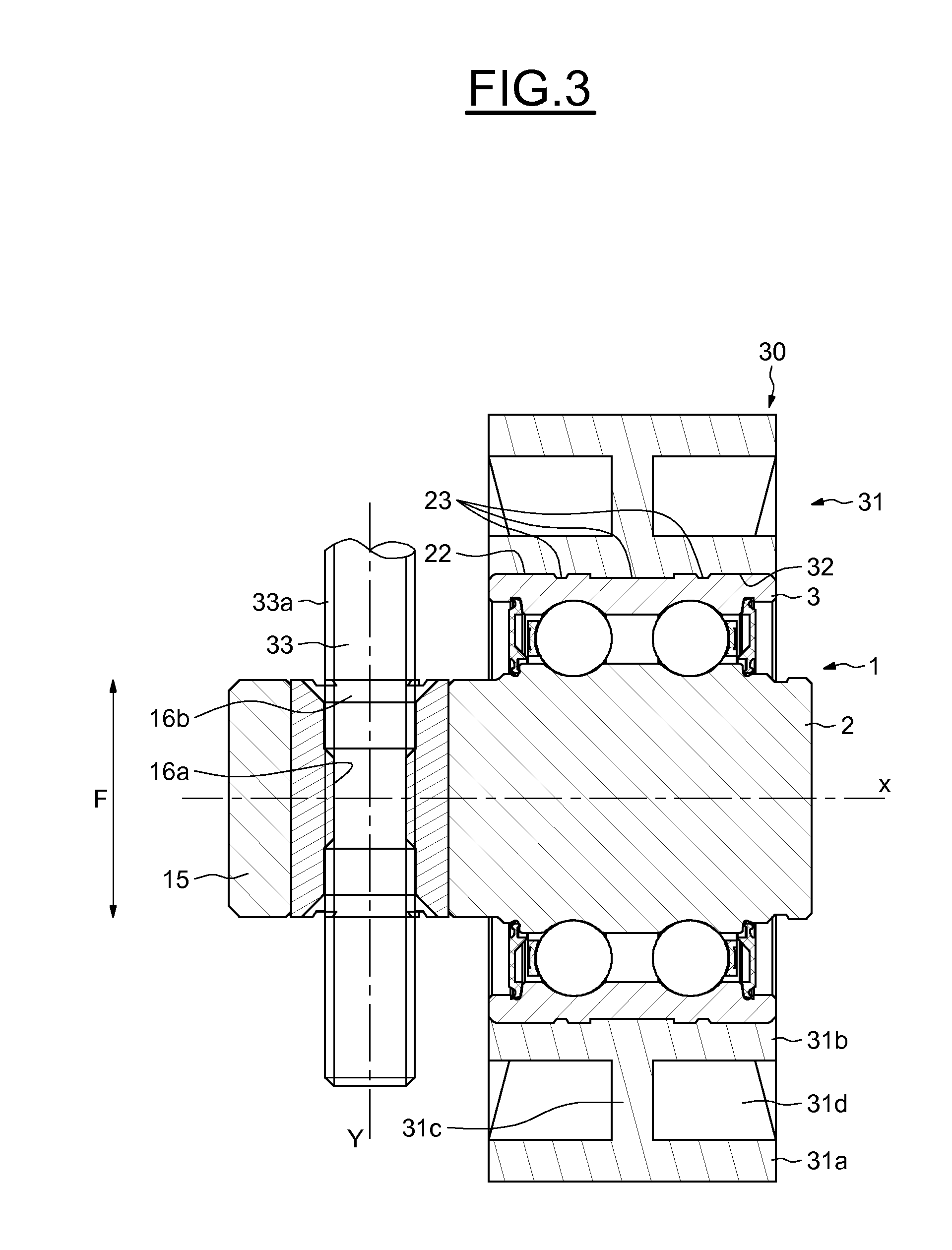
[0013]Therefore, the threading operations are not carried out directly on the inner race. Moreover, the mounting of the insert on the inner race can be carried out after the surface treatment of the latter, and notably after the assembly of the other elements of the rolling bearing, which reduces the risk of a defect of perpendicularity between the axis of the rolling bearing and the axis of the threaded rod interacting with the insert. The tolerances of the threading made in the insert are also more easily maintained.

Problems solved by technology

However, when the threading is machined in the thickness of the non-rotating portion, burrs may appear on the sides of the thread.
Moreover, since the threading tolerances are difficult to maintain, a defect of perpendicularity may appear between the axis of the rolling bearing and the axis of the tapped hole.
Moreover, the surface treatment conventionally carried out on the non-rotating portion, forming the inner race of the rolling bearing, may cause a weakness or even a breakage of the threading.
The failure of a belt, in particular of a timing belt of a motor vehicle heat engine may cause considerable damage to the engine and compromise operating safety.

Method used


Image

  • Rolling bearing for tensioning roller device and associated tensioning roller
  • Rolling bearing for tensioning roller device and associated tensioning roller
  • Rolling bearing for tensioning roller device and associated tensioning roller

Examples


Embodiment Construction

[0028]As illustrated in FIGS. 1 and 2, the rolling bearing 1, on the axis X, comprises an inner race 2, an outer race 3, two rows of rolling elements 4, 5, in this instance made in the form of balls, placed between raceways of the inner race 2 and outer race 3, two cages 6, 7 respectively maintaining the circumferential spacing of the rolling elements 4, 5, and two flanges or seals 8, 9 that are symmetrical relative to a radial plane passing between the two rows of rolling elements 4, 5.

[0029]It will be noted that it would be possible to have a single row of rolling elements placed between the races 2 and 3.

[0030]The inner race 2 forms the non-rotating portion of the rolling bearing 1 and comprises an axi-symmetric outer surface 10 in which toroidal raceways 11, 12 are made for the rolling elements 4, 5 and annular channels 13, 14 for making contact with lips 8a, 9a of the seals 8, 9. The inner race 2 also comprises an axial portion 15 extending axially, when considering the axis X ...


PUM

PropertyMeasurementUnit
diameteraaaaaaaaaa
lengthaaaaaaaaaa
tensionaaaaaaaaaa

Abstract

Rolling bearing, for a tensioning roller, comprising an inner race, an outer race mounted so as to rotate about the inner race and at least one row of rolling elements placed between the inner race and outer race, the said inner race comprising an axial portion extending axially beyond the outer race.The rolling bearing comprises an insert fitted into an open-ended bore made in the axial portion of the inner race.

Description

CROSS-REFERENCE[0001]This application claims priority to French Application No. FR1060189 filed on Dec. 7, 2010.FIELD OF THE INVENTION[0002]The present invention relates to the field of rolling bearings for tensioning roller devices designed to interact with a chain or a belt. Tensioning rollers are usually used to adjust and constantly maintain a tension on a belt within a determined range or to modify the orientation of the strands of a belt.BACKGROUND OF THE INVENTION[0003]Such rollers are notably used, for example, with timing belts or belts for driving accessories, in an internal combustion heat engine of a motor vehicle, for example.[0004]The invention relates more particularly to the tensioning rollers comprising a pulley mounted rotatably on a non-rotating spindle or shaft that can be moved radially so that the pulley applies an appropriate tension to the belt with which it is in contact. The radial movement of the spindle or the shaft can be adjusted by a screw mechanism in...

Claims


Application Information

Patent Timeline
Patent Type & Authority Applications(United States)
IPC IPC(8): F16H7/12F16H7/08F16C33/72F16C33/58F16C19/08
CPCF16C13/006F16C19/08F16H7/18F16H2007/0865F16H2007/088F16C33/7856F16C2361/63F16C35/067Y10T29/49684F16C3/02F16C35/06F16C43/04
Inventor LESCORAIL, ROMUALDROBERT, ERIC
Owner AB SKF
Learn More