Surgical tools for treatment of spinal stenosis

a technology for spinal stenosis and surgical tools, applied in the field of surgical tools for treating spinal stenosis, can solve the problems of many challenges, reduced or even no direct visualization, and the development of less invasive surgical methods and devices

Inactive Publication Date: 2012-06-07
BAXANO SURGICAL
View PDF3 Cites 52 Cited by
  • Summary
  • Abstract
  • Description
  • Claims
  • Application Information

AI Technical Summary

Benefits of technology

[0042]As mentioned, the activating step may further include activating the pullwire lock such that the locked pullwire can transmit between 10 and 60 pounds without slippi

Problems solved by technology

Developing less invasive surgical methods and devices, however, can pose many challenges.
For example, some challenges of less invasive techniques include working in a smaller operating field, working with smaller devices, and trying to operate with reduced or even no direct visualization of the structure (or structures) being treated.
These challenges are compounded by the fact that target tissues to be modified often reside very close to one or more vital, non-target tissues, which the surgeon hopes not to damage.
One of the initial obstacles in any given minimally invasive procedure, therefore, is positioning a minimally invasive surgical device in a desired location within the patient to perform the procedure on one or more target tissues, while avoiding damage to nearby non-target tissues.
In a patient, this may manifest as pain, impaired sensation and/or loss of strength or mobility.
Epidural steroid injections may also be utilized, but they do not provide long lasting benefits.
When these approaches are inadequate, current treatment for spinal stenosis is generally limited to invasive surgical procedures to remove ligament, cartilage, bone spurs, synovial cysts, cartilage, and bone to provide increased room for neural and neurovascular tissue.
Removal of vertebral bone, as occurs in laminectomy and facetectomy, often leaves the effected area of the spine very unstable, leading to a need for an additional highly invasive fusion procedure that puts extra demands on the patient's vertebrae and limits the patient's ability to move.
Unfortunately, a surgical spine fusion results in a loss of ability to move the fused section of the bac

Method used


Image

  • Surgical tools for treatment of spinal stenosis
  • Surgical tools for treatment of spinal stenosis
  • Surgical tools for treatment of spinal stenosis

Examples


Embodiment Construction

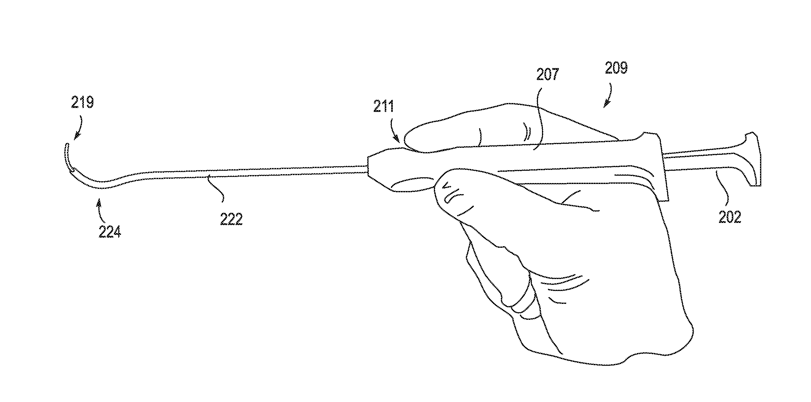
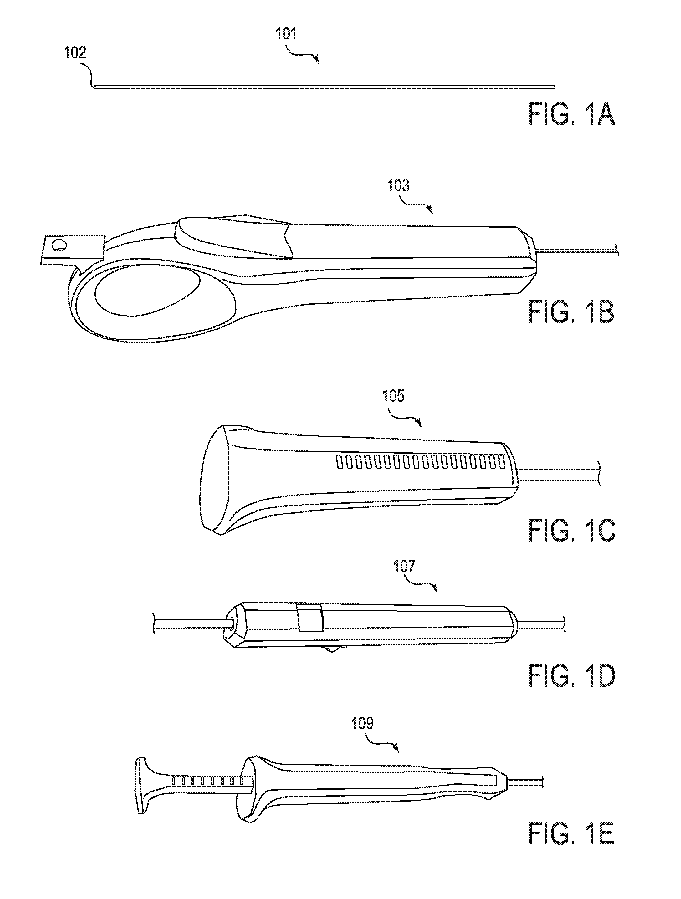
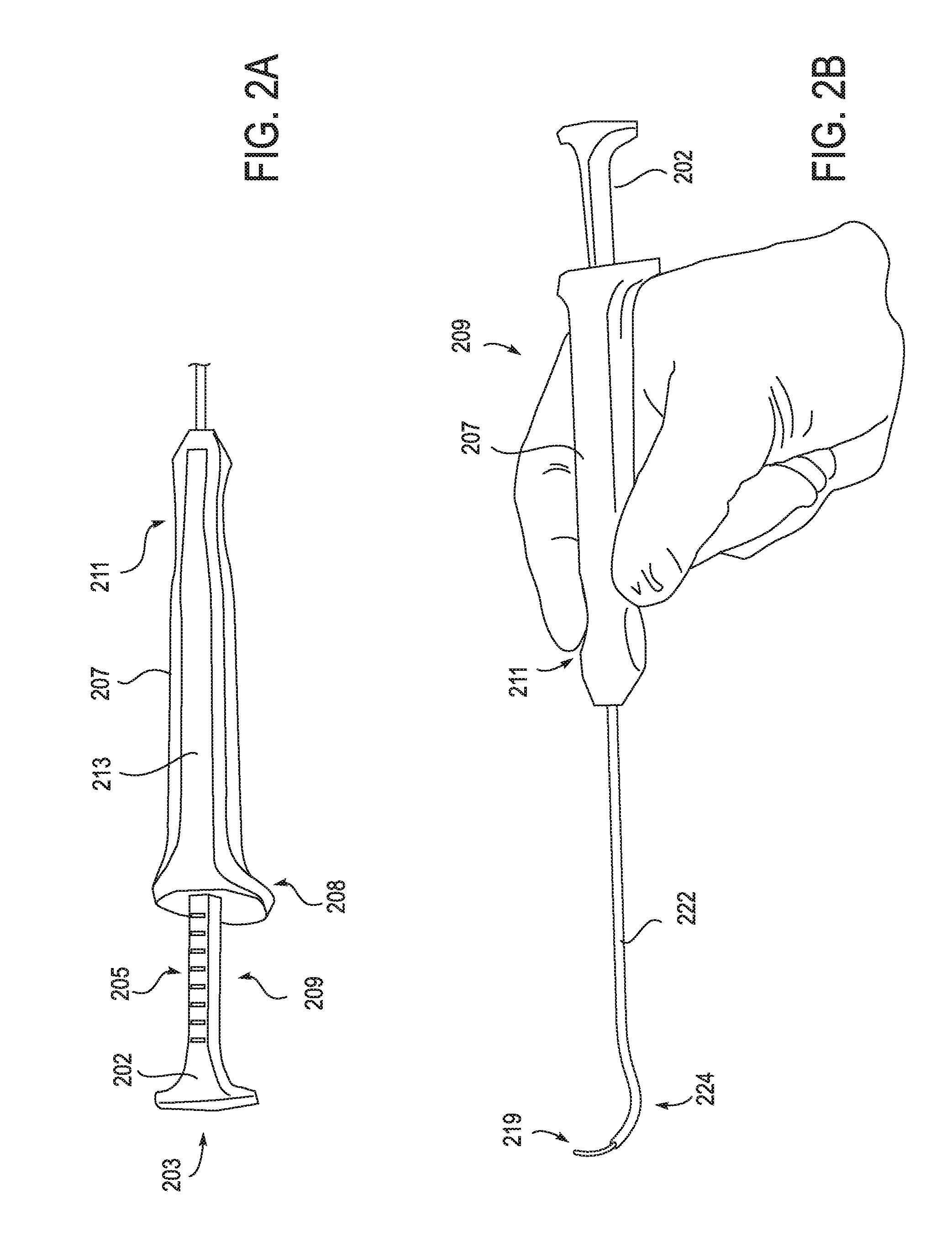
[0138]The devices, systems and methods described herein may be used in any appropriate surgical procedure, particularly for the surgical treatment of spinal stenosis. For example, described herein are systems including one or more of the following devices: a pullwire, a handle for the distal end of a pullwire, a probe for positioning a pullwire, a neural localization device for use with a pullwire and a tissue modification device for use with the pullwire.

[0139]In particular, described herein are devices and systems including these devices that are configured for use together as a system. For example, the devices described herein may all be coordinated so that they may function together, and may include markings, orienting structures and other features that are common between the different devices within the system. In some variations the devices all include front / back, top / bottom, or other orientation structures on the handles of the devices. The handles may be structured in common...


PUM


Abstract

Described herein are devices and methods for positioning a wire around a target tissue. In some embodiments, a probe device includes a rigid outer cannula having a curved distal region and a flexible inner cannula slideably disposed within the rigid outer cannula, wherein the inner cannula is configured to assume a curved shape when extended distally from the outer cannula. In some embodiments, the probe device further includes a distal tip at the distal end of the inner cannula and a safety retainer cable coupled to the distal tip and secured to the probe proximally from the distal end of the safety retainer; wherein the safety retainer cable extends proximally from the distal tip and is slack. In some embodiments, the inner cannula comprises an elongate body with a longitudinally extending support member and a longitudinally extending tubular body, configured to pass a wire, disposed inside the elongate body.

Description

CROSS REFERENCE TO RELATED APPLICATIONS[0001]This patent application is a continuation-in-part of U.S. patent application Ser. No. 12 / 824,043, titled “SURGICAL TOOLS FOR TREATMENT OF SPINAL STENOSIS”, filed on Jun. 25, 2010, now Publication No. US-2010-0331900-A1, which claims priority to U.S. Provisional Patent Application No. 61 / 220,314, titled “SURGICAL TOOLS FOR TREATMENT OF SPINAL STENOSIS”, filed on Jun. 25, 2009 and U.S. Provisional Patent Application No. 61 / 253,811, titled “SURGICAL TOOLS FOR TREATMENT OF SPINAL STENOSIS”, filed on Oct. 21, 2009.[0002]This patent application also claims priority to U.S. Provisional Patent Application No. 61 / 427,449, titled “TISSUE REMOVAL DEVICES AND METHODS”, filed on Dec. 27, 2010. These patent applications are each incorporated by reference in their entirety.INCORPORATION BY REFERENCE[0003]All publications and patent applications mentioned in this specification are herein incorporated by reference in their entirety to the same extent as i...

Claims


Application Information

Patent Timeline
IPC IPC(8): A61B17/68
CPCA61B17/00234A61B17/1659A61B2017/320044A61B2017/00469A61B2017/0256A61B17/1671
Inventor WALLACE, MICHAEL P.LEGUIDLEGUID, ROYLEGUIDLEGUID, RONALDCANTORNA, NESTOR C.
Owner BAXANO SURGICAL
Why Eureka
Try Eureka