Modular hip stem system

Inactive Publication Date: 2012-06-07
HOWMEDICA OSTEONICS CORP
View PDF2 Cites 5 Cited by
  • Summary
  • Abstract
  • Description
  • Claims
  • Application Information

AI Technical Summary

Benefits of technology

[0011]The key difference for the system of the present invention is that a single stem size can have variations in the position of the mating feature for the modular neck and this leads to the ability to give the patient more head medial-lateral offset without changing the neck length, neck angle and / or proximal-distal head position. An alternate embodiment shifts only the P-D head location without changing the M-L location.
[0015]The modular stem / neck design with two or more mating pocket positions for each stem size allows a surgeon to reconstruct leg length and medial-lateral head offset without adding extra neck length in patients who have a higher than average head position and corresponding medial canal offset values along the length of the calcar. This results in a stronger system with a shorter moment arm.
[0016]Each stem size has multiple medial curvature options. One version of this stem design has a modular neck pocket and would utilize modular necks in a new way that will allow surgeons to attain the appropriate medial-lateral head offset range, leg length range and anteversion angle range with reduced neck lengths for patients that require high head offsets and longer then normal neck lengths.

Problems solved by technology

Such a femoral component may not be readily available for a given distal stem size within the same prosthesis system, and accordingly, may involve consideration of a long lead-time custom device, or more probably, consideration of another prosthesis system may have to be explored.
The former technique for seating the femoral component at a higher position can result in larger stem / bone interface gaps proximal-medially, a condition reflective of a less desirable, and possibly less stable, stem fit.
Lower prosthesis seating may also result in an inexact fit between the stem and bone, especially if the femur was surgically prepared for a larger proximal stem design of different proximal-medial curvature.
However, a disadvantage to these systems is that they do not allow a surgeon to trial off of the actual stem implant.
The disadvantages to these modular stem-neck implant systems is that due to the junction between the two mating parts the resulting implant may not be as strong as a monolithic implant of the same geometry.
Neck designs in both monolithic and modular stem designs are subjected to a very high amount of stress when loaded in the hip.
Current modular neck designs have been developed with relatively expensive materials that are much stronger in order to deal with this high stress.
In some cases, modular neck length is also limited for a given set of stem sizes due to the maximum stress limits of the materials that are currently used.
This results in a lack of appropriate head offset values for some patient's anatomy.

Method used


Image

  • Modular hip stem system
  • Modular hip stem system
  • Modular hip stem system

Examples


Embodiment Construction

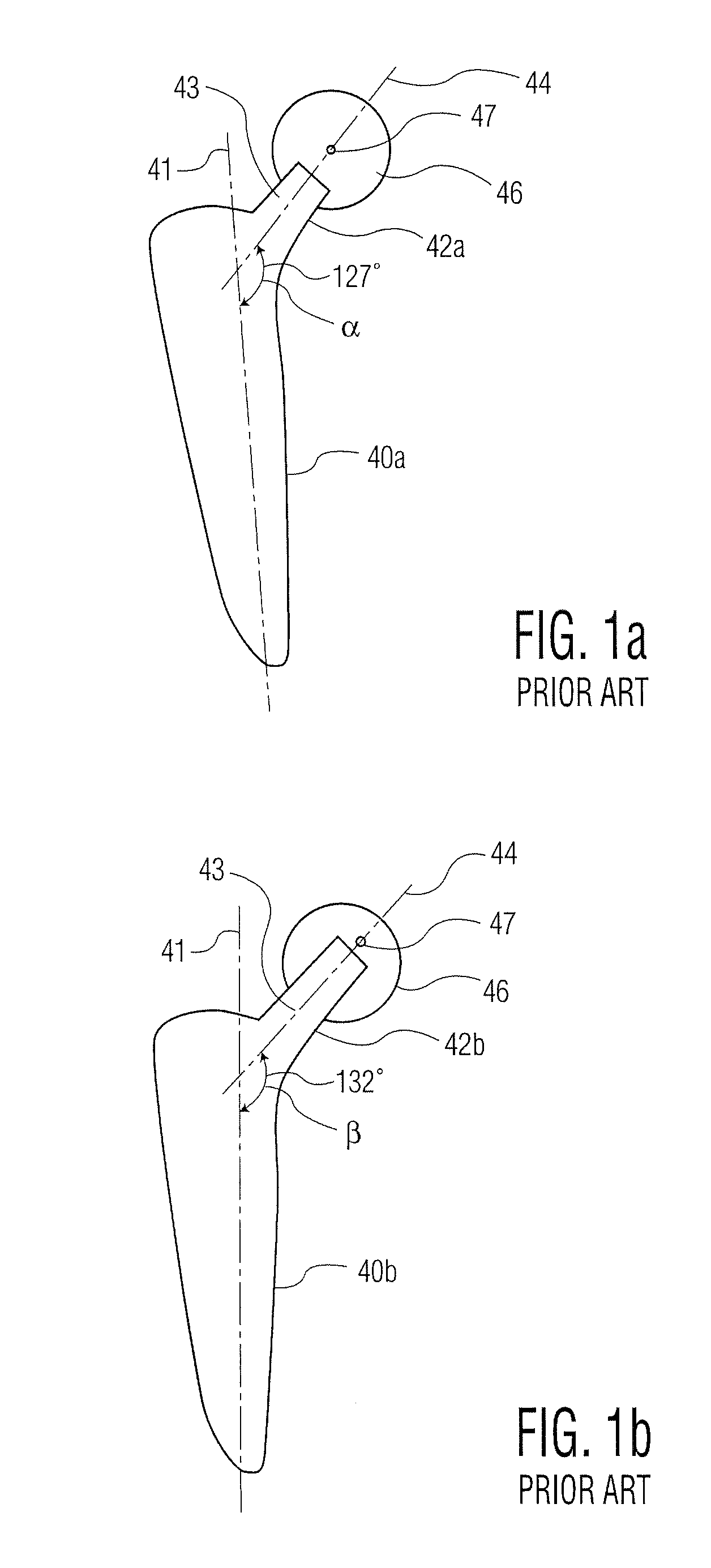
[0032]Referring to FIGS. 1a and b there is shown a first stem component 40a and a second stem component 40b. Stems 40a, 40b include a longitudinal axis 41, which extends in a generally proximal-distal direction. Stems 40a and 40b include necks 42a and 42b having a trunion 43 at the proximal most end thereof. Necks 42a, 42b extent along an axis 44. In the stem of FIG. 1a, the angle between axis 44 and axis 41 is proximally a 127°, whereas in FIG. 1b it is 132°. A part-spherical modular head 46 is utilized on both necks 42a and 42b. Heads 46 has a center 47. Because the neck angle alpha (127°) and beta (132°) are different, the location of head center 47 changes both in a proximal-distal direction and in a medial-lateral direction. This is one way that the prior art has addressed changing the center of rotation of prosthetic femoral component with respect to a prosthetic acetabular component.

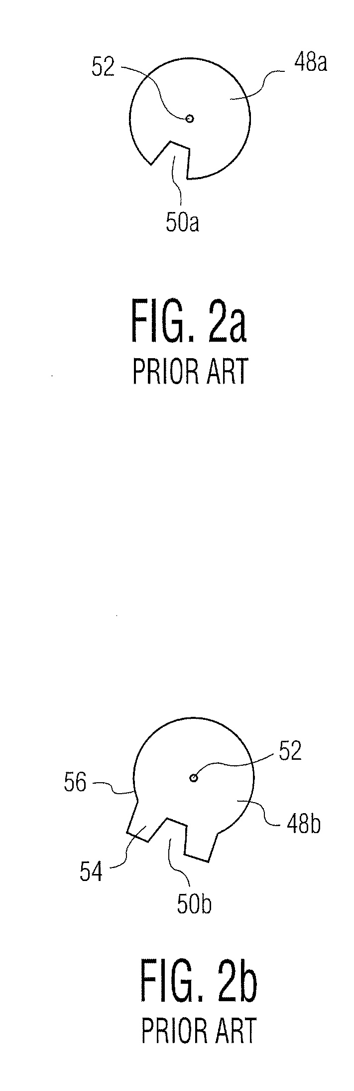
[0033]A second way of changing the center location is shown in FIGS. 2a and 2b, which show two...


PUM


Abstract

A kit of modular prosthetic hip components includes a first neck having a coupling element thereon. First and second hip stems each have a coupling element at a proximal end thereof for connecting to the coupling element of the first neck. The first and second hip stems have a progressively larger medial-lateral dimension in a proximal portion thereof. The coupling element on each of the first and second hip stems is located at a different medial-lateral location thereon with the coupling element located more medially and proximally on the second stem than the first stem. The first neck forms an identical first neck angle with a proximal-distal axis of the respective first and second stems. The coupling elements on the first and second stems locate a head mounted on the first neck in the same proximal-distal location but a different medial-lateral location with respect to an acetabulum.

Description

BACKGROUND OF THE INVENTION[0001]This invention relates generally to a system of modular femoral components for a hip joint prosthesis and, more particularly, is directed to the shape of the intramedullary stem which is inserted into the surgically prepared medullary canal of the proximal femur for fixation or anchorage of the prosthesis into the surrounding supportive cortical bone and also relates to the location for insertion of a neck element into the stem.[0002]As is well-known in the art, the intramedullary stem or blade-like portion of the femoral component of a hip joint prosthesis is inserted into the prepared medullary canal of the proximal femur for fixation within the surrounding bone structure. This fixation occurs by either bone cementing which employs methyl methacrylate, or by biological fixation employing a mechanism of bone ingrowth within minute voids or porosities of a specially applied porous-like metal alloy surface structure. This porous surface structure is m...

Claims


Application Information

Patent Timeline
IPC IPC(8): A61F2/36
CPCA61F2/3662A61F2002/30538A61F2002/3678A61F2002/30616A61F2002/3652A61F2002/30553
Inventor RICKELS, TRACYHUFFNAGLE, WILLIAM
Owner HOWMEDICA OSTEONICS CORP
Why Eureka
Try Eureka