Accelerator pedal apparatus

a pedal apparatus and accelerator technology, applied in the direction of mechanical control devices, instruments, process and machine control, etc., can solve the problem of high cost and achieve the effect of drastically reducing cos

Active Publication Date: 2012-06-07
MIKUNI CORP
View PDF10 Cites 35 Cited by
  • Summary
  • Abstract
  • Description
  • Claims
  • Application Information

AI Technical Summary

Benefits of technology

[0008]In view of the above, the present disclosure provides an accelerator pedal apparatus capable of accurately controlling a torque motor without disposing MPS means which detects a rotational angle of the torque motor even when the torque motor is utilized as a drive source of an active control mechanism.
[0015]According to the present disclosure, when an upper device commands to apply operational reaction force, the reaction force controller is configured to apply operational reaction force by controlling driving of the torque motor based on the accelerator opening rate. Accordingly, the present disclosure provides an effect that the torque motor can be surely controlled without disposing means to detect the rotational angle of the torque motor. In addition, since the MPS is not utilized, it is possible to obtain an effect that cost is drastically reduced.

Problems solved by technology

Accordingly, there is a problem of high cost.
Further, in the accelerator pedal apparatus, the reaction force controller may not generate the operational reaction force without driving the toque motor when the accelerator opening rate which is detected by the accelerator position detector is a predetermined opening rate or lower.

Method used


Image

  • Accelerator pedal apparatus
  • Accelerator pedal apparatus
  • Accelerator pedal apparatus

Examples


first embodiment

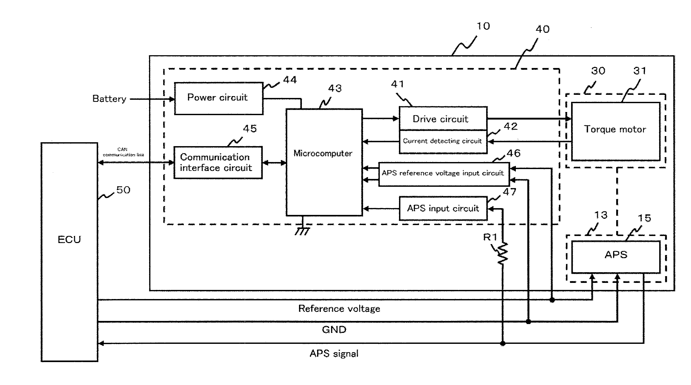
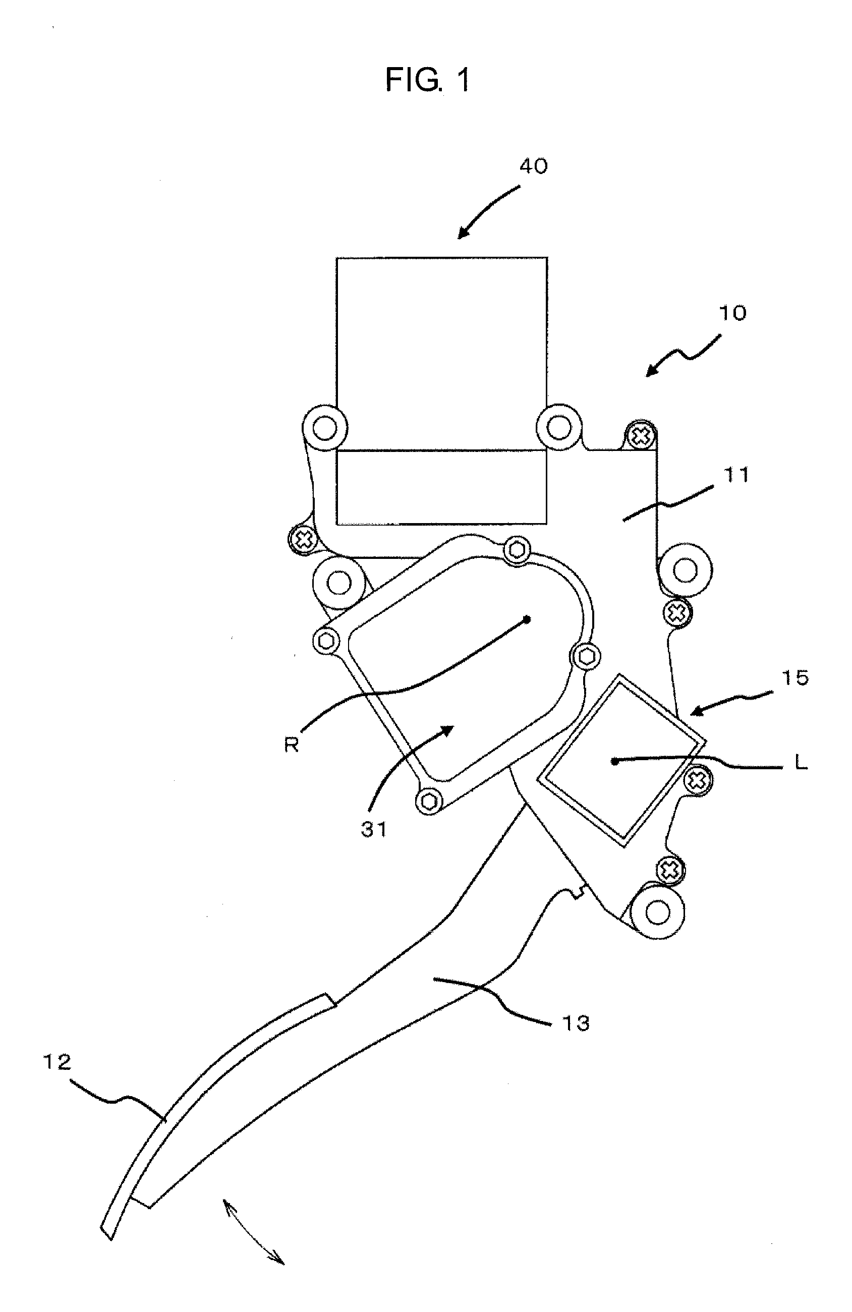
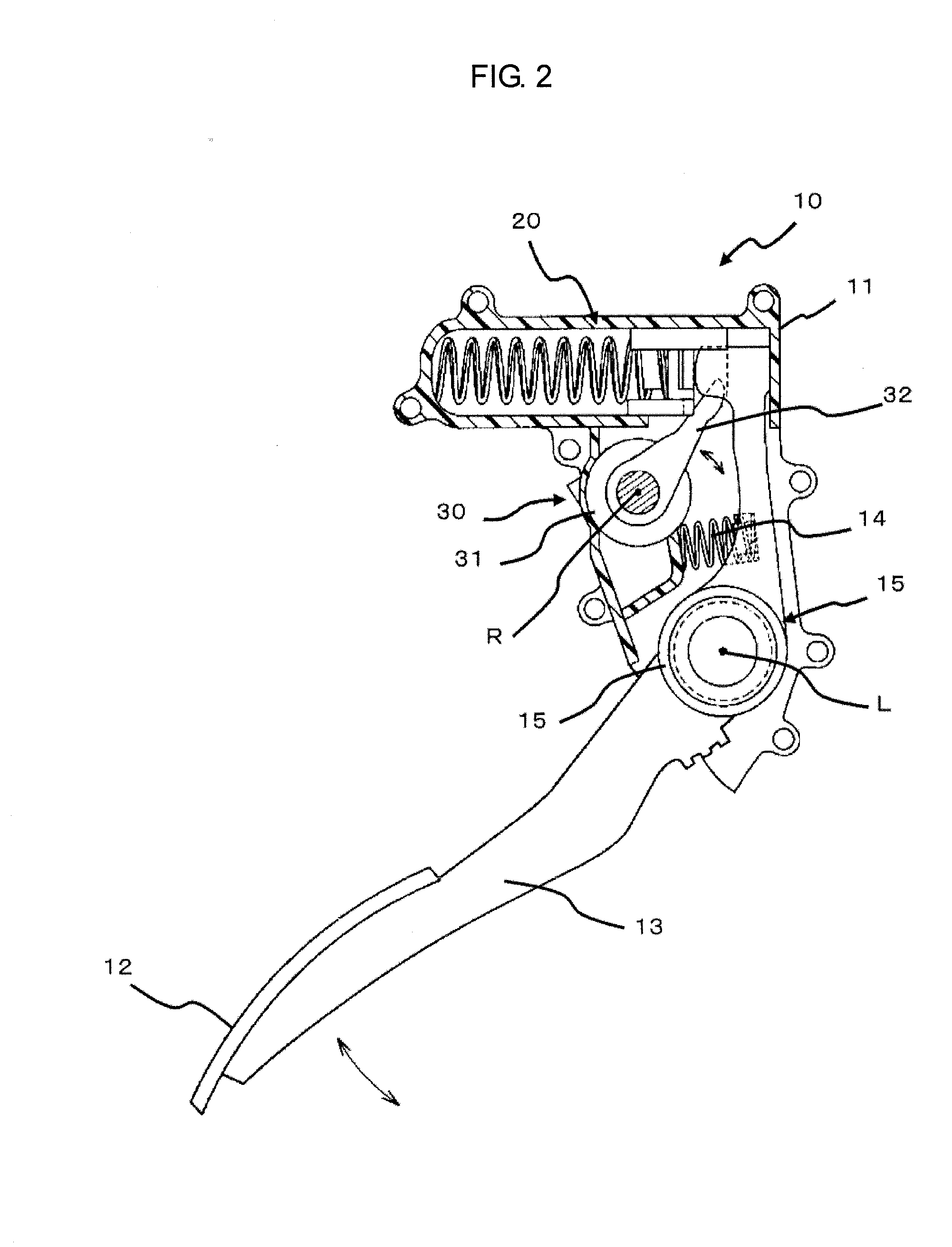
[0026]An accelerator pedal apparatus 10 of the first embodiment is an accelerator pedal apparatus applied for an electronic control throttle system (i.e., a drive-by-wire system), and includes a housing 11 which is attached to a vehicle body of an automobile and the like, a pedal arm 13 which is swingably supported by the housing 11 as having an accelerator pedal 12, a return spring 14 which applies operational reaction force by applying urging force to return the pedal arm 13 to a rest position, a hysteresis generating mechanism 20 which generates hysteresis at the operational reaction force, an accelerator pedal position sensor (APS) 15 which detects a rotational angle of the pedal arm 13 as an accelerator opening rate due to operation of the accelerator pedal 12 and which outputs the detected accelerator opening rate to an engine control unit (ECU) 50 being an upper device as an APS signal, an active control mechanism 30 which varies the operational reaction force corresponding t...

second embodiment

[0047]Next, the present disclosure will be described with reference to FIG. 7.

[0048]An accelerator pedal apparatus 10a of the second embodiment differs from the first embodiment in that the reference voltage to be supplied from the ECU 50 to the APS 15 and the GND voltage to be supplied from the ECU 50 to the APS 15 are supplied to the APS reference voltage input circuit 46 respectively via a resistance R2 and a resistance R3 and that the GND voltage to be inputted to the APS reference voltage input circuit 46 is corrected by utilizing a resistance R4 and a resistance R5.

[0049]The APS reference voltage input circuit 46 is connected via the resistance R2 to a power line through which the reference voltage is supplied from the ECU 50 to the APS 15, so that the reference voltage is supplied via the resistance R2. Further, the APS input circuit 47 is connected via the resistance R3 to a GND line through which the GND voltage is supplied from the ECU 50 to the APS 15, so that the GND vol...


PUM


Abstract

An accelerator pedal apparatus includes a torque motor which generates operational reaction force corresponding to operation of an accelerator pedal, an accelerator pedal position sensor (APS) which detects an accelerator opening rate of an accelerator pedal and outputs the accelerator opening rate to an engine control unit (ECU) being an upper device, and a control unit which applies the operational reaction force as controlling driving of the torque motor. The control unit applies the operational reaction force as controlling driving of the torque motor based on the accelerator opening rate when being commanded to apply the operational reaction force by the ECU.

Description

CROSS-REFERENCE TO RELATED APPLICATIONS[0001]This application claims the priority benefit of Japanese Patent Application No. 2010-268437, filed Dec. 1, 2010, in the Japanese Patent Office, the disclosure of which are incorporated herein by reference.BACKGROUND[0002]1. Field[0003]The present disclosure relates to an accelerator pedal apparatus which is applied for a vehicle such as an automobile, and in particular, relates to an accelerator pedal apparatus including an active control mechanism which draws driver's attention by varying operational reaction force against accelerator pedal operation.[0004]2. Description of the Related Art[0005]Recently, accelerator pedal apparatuses including an active control mechanism which draw a driver's attention by varying operational reaction force against accelerator pedal operation have been developed and applied for vehicles such as automobiles. For example, Japanese Patent Publication No. 2010-111379 proposes an accelerator pedal apparatus ca...

Claims


Application Information

Patent Timeline
Patent Type & Authority Applications(United States)
IPC IPC(8): G06F7/00B60K26/02G05G5/03H02P29/00
CPCB60K26/021G05G1/38Y10T74/20534B60K2026/023G05G5/03
Inventor YAMAZAKI, SHIGERUTOUHACHI, HIROMUTSU
Owner MIKUNI CORP
Why Eureka
Try Eureka