
Subsurface Vortex Assisted Distributed Propulsion Active Hull

a distributed propulsion and active hull technology, applied in underwater equipment, special-purpose vessels, vessel construction, etc., can solve the problems of increasing drag and noise, and increasing hydrodynamic noise and cavitation around the propulsion system, so as to reduce drag and hydrodynamic noise and increase thrust

Inactive Publication Date: 2012-06-14
KING RON M
View PDF1 Cites 10 Cited by
  • Summary
  • Abstract
  • Description
  • Claims
  • Application Information

AI Technical Summary

Benefits of technology

[0043]A submersible vehicle, apparatus and method utilizing the Active Hull Platform to decrease drag and hydrodynamic noise while increasing thrust through boundary layer vortex control and distributed propulsion.

Problems solved by technology

As these eddies are shed or separate from the craft they do so at great expense or drag to the efficient fore-aft motion of the craft.
With Fixed Hulls, all net drag forces traditionally are overcome by the propeller or centralized propulsion system which as the craft increases in size and speed increases the problem of hydrodynamic noise and cavitation around the propulsion system.
The application of power to the rear of a craft creates an inverted pendulum, with stability and guidance problems.
The application of power or guidance to the forward position of a craft cause turbulent flows that increase drag and noise aft down the length of the craft.
This frontal wave generation limits stability, efficiency and speed.
Most importantly the more concentrated approach to thrust gives an uneven pulsating noisy result.
They require large pumps or propellers that would cause large Reynolds numbers and noisy cavitation in an underwater craft.
They do not satisfy the “distributed” portion of the definition because when motionless they cover little surface area as seen from above and they do not address drag.
However his invention does not address the direction of bulk flow over the hull and therefore has no opportunity to create some advantage from specific VG.
He would also have a very noisy system particularly if he employed the supercavity characteristics he describes.
However, the state of the art for craft utilizing vortices and flexible dynamic hulls is far from delivering large payloads under harmful conditions.
These designs have limitations as to its velocity and effectiveness as an underwater craft.
But none accomplish the mission of propelling a rugged high velocity underwater craft or device utilizing boundary layer forces and distributed propulsion while avoiding the noise of cavitation.

Method used


Image

  • Subsurface Vortex Assisted Distributed Propulsion Active Hull
  • Subsurface Vortex Assisted Distributed Propulsion Active Hull
  • Subsurface Vortex Assisted Distributed Propulsion Active Hull

Examples


Embodiment Construction

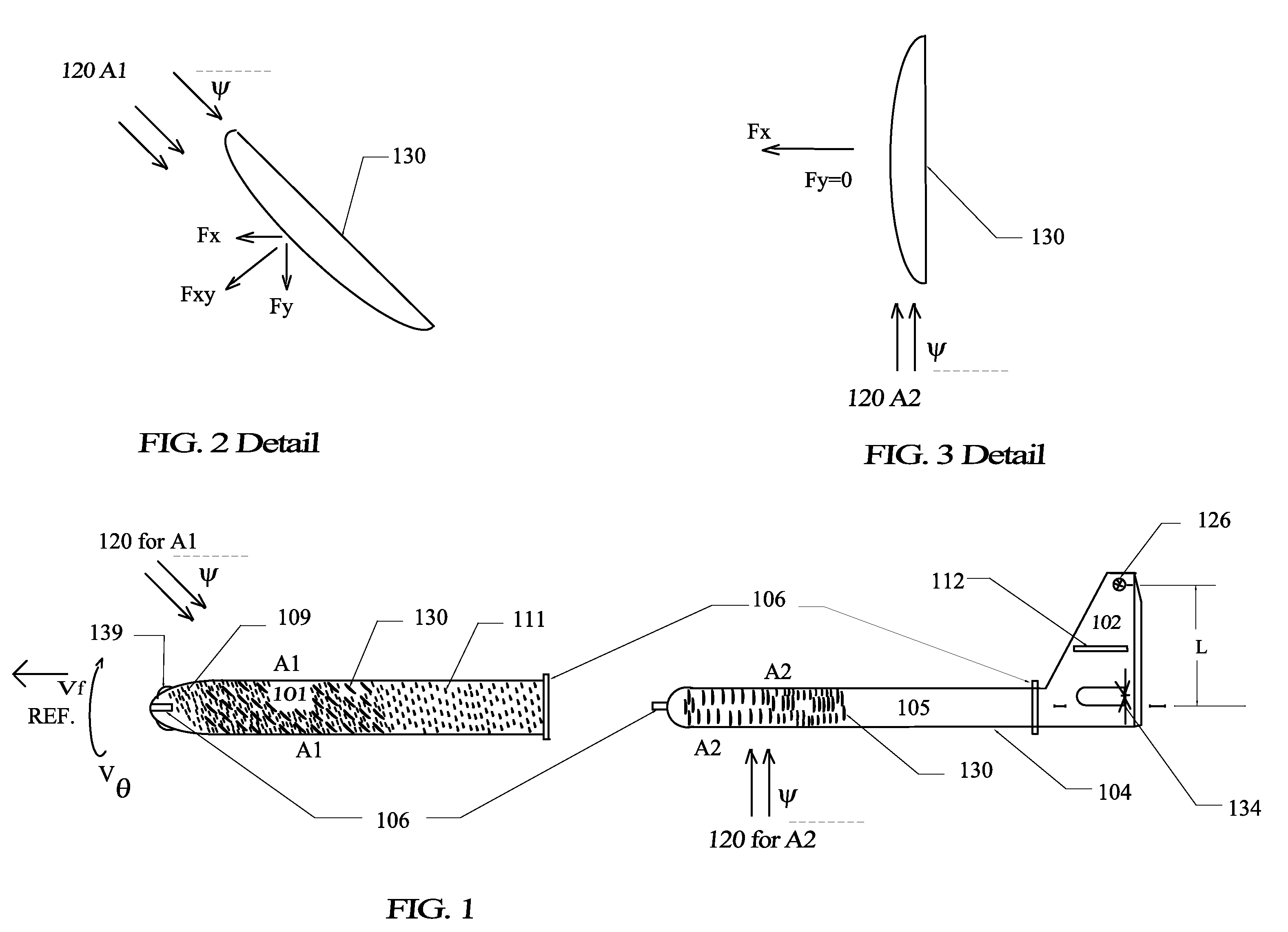
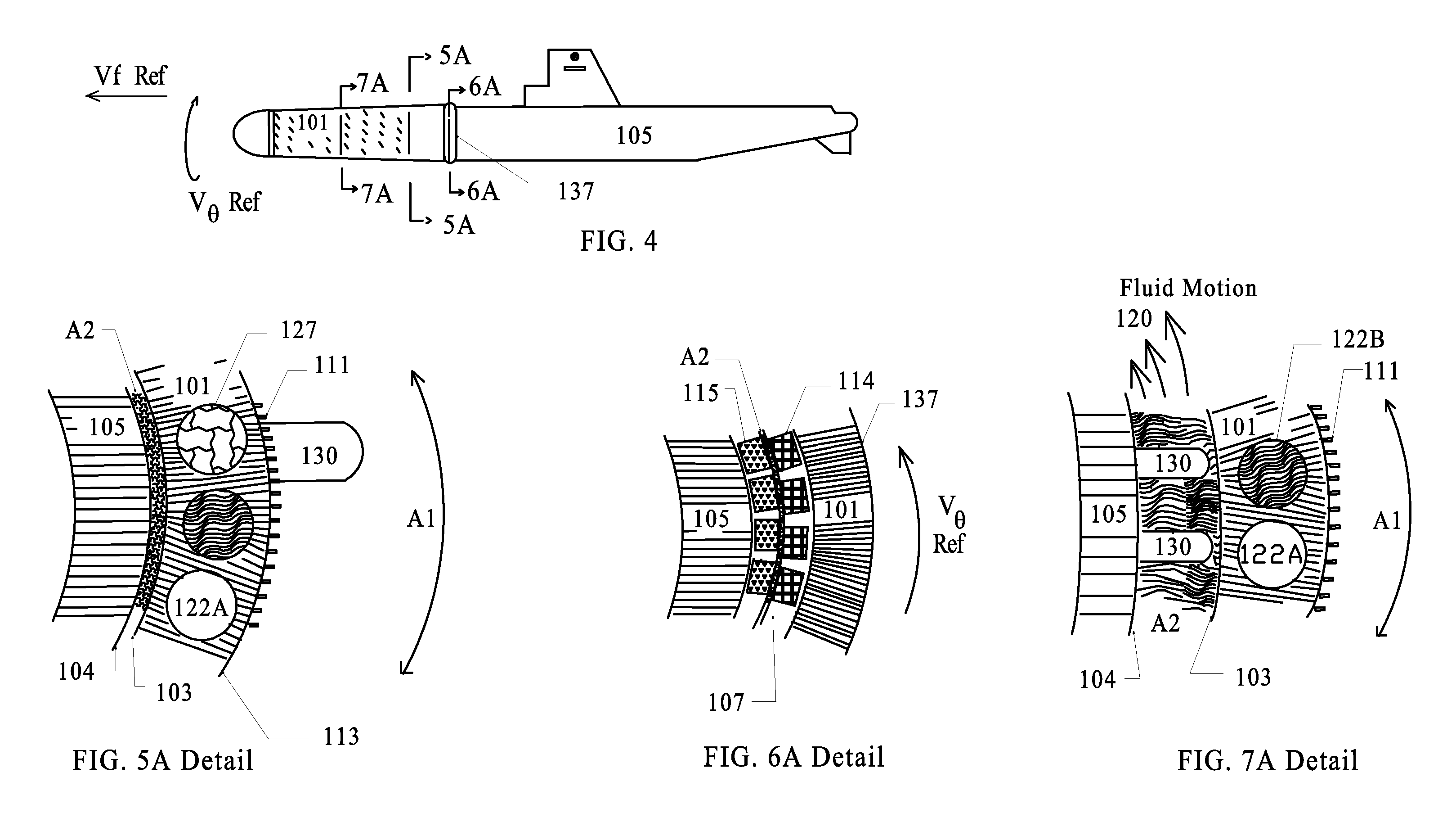
[0120]In the following detailed description of the invention, numerous specific details are provided for a thorough understanding of the invention. However, it will be appreciated by those skilled in the art that the invention may be practiced without utilizing every one of these details in any one embodiment. In addition, well-known methods, procedures, materials, components and circuitry have not been described in elaborate detail to avoid an unnecessary obscuring of the invention. Many of these “means” are described by those in “related art” and as such are included as if written herein. However enough information is given so a Craft could be built and methods could be followed using the information contained herein along with state of the art methods and materials. The reference materials included herein and simplified drawings attached hereto and made a part hereof in absence of the ability to present a working model are deemed the best way to concisely convey the substance of ...


PUM


Abstract

High velocity subsurface craft, apparatus or method positively affecting propulsion and limiting drag by the use of a rotating body with selected Surface Treatment. The Active Hull Platform provides Apparent Flows that allow for shorter more dispersed blade arrays and boundary layer management that impacts vorticity on skin surfaces by controlling the angular momentum of the vortices formed. By converting drag forces into thrust, vortices need not be avoided and an even non pulsating distributed thrust is the result.

Description

CROSS-REFERENCE TO RELATED APPLICATIONS[0001]NoneGOVERNMENT INTEREST[0002]NoneJOINT RESEARCH[0003]NoneSEQUENCE LISTING[0004]NoneBACKGROUND OF THE INVENTIONA. Field of the Invention[0005]The field of this invention relates generally to drag, stealth, vortices, and propulsion in subsurface craft. More specifically it relates to managing specific Apparent Flows over selected Surface Treatment to exploit those forces available and generate distributed propulsion in underwater craft and devices.B. Description of Related Art[0006]U.S. Pat. No. 4,516,747 Lurz, 1985, Method of and apparatus for controlling the boundary layer flow over the surface of a body[0007]U.S. Pat. No. 5,791,275 Bandyopadhyay, 1998, Surface layer comprising micro-fabricated tiles for electromagnetic control of fluid turbulence in sea water.[0008]U.S. Pat. No. 4,812,251 Stangroom, 1989, Electro-rheological fluids / electric field responsive fluids[0009]U.S. Patent 20070175380 Au, 2007, Water craft with new configuration ...

Claims


Application Information

Patent Timeline
Patent Type & Authority Applications(United States)
IPC IPC(8): B63G8/08B63G8/22
CPCB63B1/107B63G8/08B63G8/26B63H1/12B63H5/00Y02T70/121F42B19/125B63B2001/345B63H2001/122B63H2023/005F42B10/38Y02T70/10
Inventor KING, RON M.
Owner KING RON M
Learn More