Seat adjustment device and aircraft or spacecraft

Active Publication Date: 2012-06-14
AIRBUS OPERATIONS GMBH
View PDF33 Cites 25 Cited by
  • Summary
  • Abstract
  • Description
  • Claims
  • Application Information

AI Technical Summary

Benefits of technology

[0019]According to a further preferred configuration of the seat adjustment device of the invention, the seat connection is mounted such that it can slide and/or roll on the seat rail, the seat connection preferably comprising rolling bodies which are supported on the head portion of the seat rail. This ensures a simple displaceability of the seat connection relative to the seat rail. Thus, an appropriate drive means, in particular an electric motor for driving the worm can be configured to be correspondingly low-powered and thus lightweight.
[0020]According to a further preferred configuration of the aircraft or spacecraft of the invention, the floor has crossbars with in each case a flange, a base portion of the seat rail being at least partly arranged in an opening in a respective flange and being connected thereto. Connection methods include, in particular friction stir welding, laser welding or electron beam welding. Due to the fact that the base portion replaces part of the flange (corresponding to the width of the recess), the useful sp

Problems solved by technology

Furthermore, the worm has a relatively small extension in a direction transverse to its axis of rotation, s

Method used


Image

  • Seat adjustment device and aircraft or spacecraft
  • Seat adjustment device and aircraft or spacecraft
  • Seat adjustment device and aircraft or spacecraft

Examples


Embodiment Construction

[0042]In the figures, the same reference signs denote identical or functionally identical components, unless indicated otherwise.

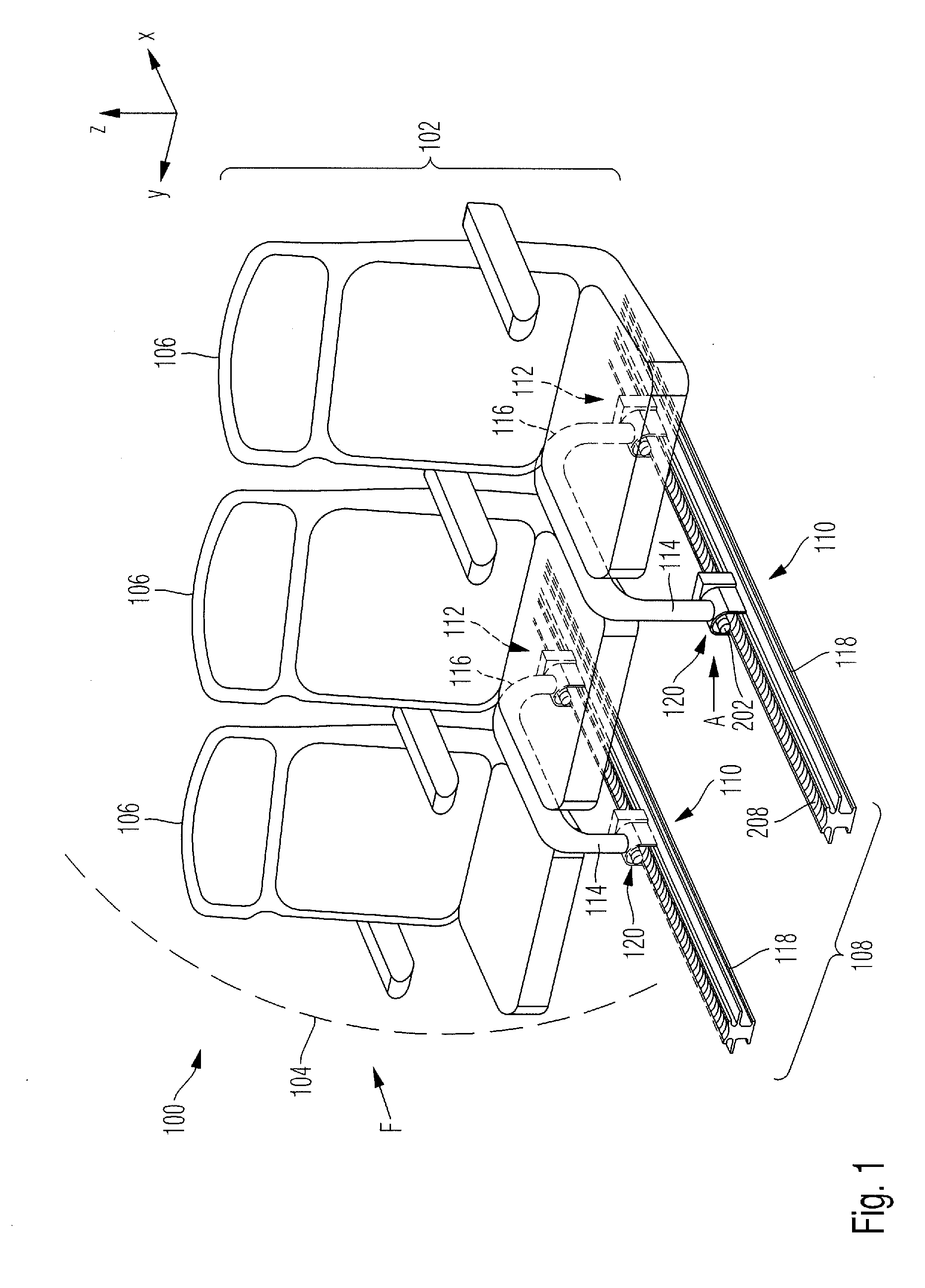
[0043]FIG. 1 is a perspective view of a detail of an aircraft, generally denoted by reference numeral 100, according to an embodiment of the present invention.

[0044]The aircraft 100 has a large number of rows 102 of seats. The rows 102 of seats are arranged behind one another in the longitudinal direction X of the aircraft 100 in a fuselage 104 of the aircraft 100. By way of example, FIG. 1 only shows one such row 102 of seats.

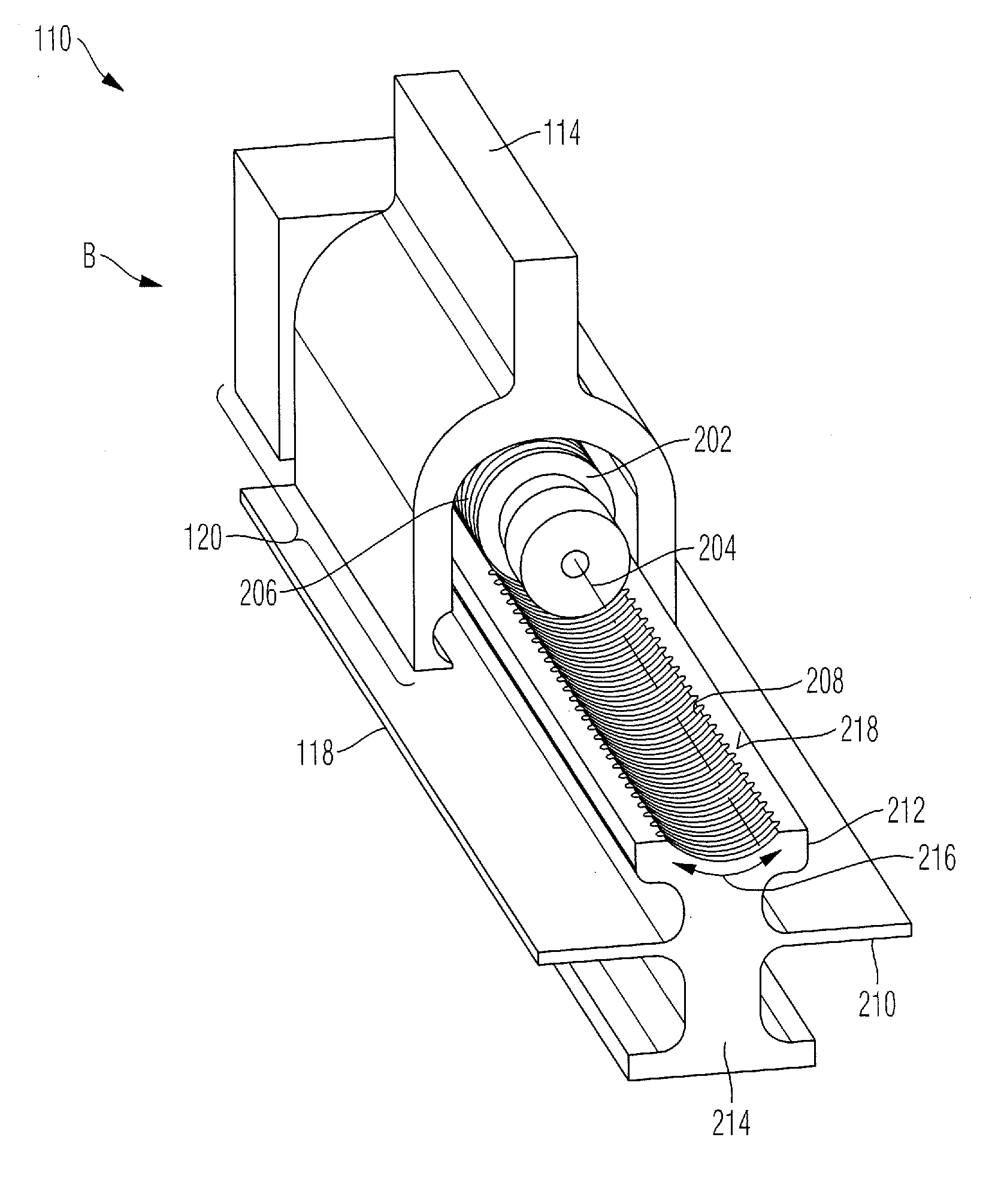
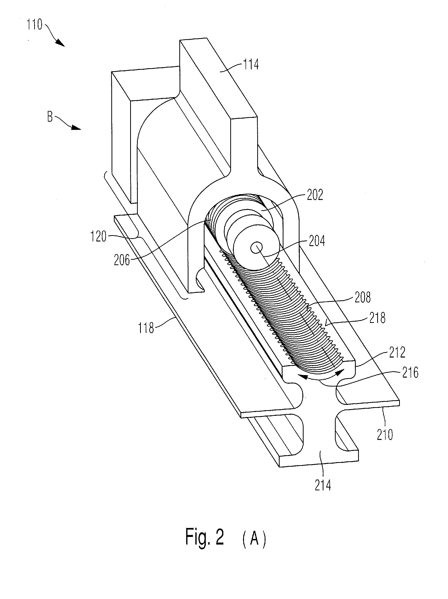
[0045]The row 102 of seats is composed of, for example, three seats 106 which are attached to a floor 108. This attachment is performed, for example by two seat adjustment devices 110 and two seat retaining devices 112. The seat adjustment devices 110 are each arranged, for example on a front leg 114 of the row 102 of seats and the seat retaining devices 112 are each arranged on a rear leg 116. “Rear” and “front” both relate to the l...


PUM


Abstract

The present invention provides a seat adjustment device for an aircraft or spacecraft, comprising:
a seat rail for connection to a floor; and
a seat connection for connection to at least one seat;
and a worm is provided which can be actuated to adjust the seat connection relative to the seat rail.

Description

CROSS-REFERENCE TO RELATED APPLICATIONS[0001]This application claims the benefit of and priority to U.S. Provisional Application No. 61 / 459,241, filed Dec. 9, 2010, and German patent application 10 2010 053 892.2 filed Dec. 9, 2010, the entire disclosures of which are herein incorporated by reference.FIELD OF THE INVENTION[0002]The present invention relates to a seat adjustment device and to an aircraft or spacecraft.[0003]Although the present invention and the problem on which it is based can be applied to any seat adjustment devices and to any aircraft or spacecraft, they will be described in detail with respect to an aircraft which has a reconfigurable cabin layout.[0004]A reconfiguration of a cabin layout of an aircraft is desirable to allow an individual adaptation of the cabin layout to requests by individual passengers or to requirements imposed by aircraft operators. The reconfiguration comprises, for example, releasing a respective seat from associated seat rails, moving th...

Claims


Application Information

Patent Timeline
IPC IPC(8): B60N2/075B60N2/90
CPCB64D11/0696B64C1/20B60N2/072B60N2/067B60N2/929B64D9/003B60N2/1871B64D11/06395B64D9/00B60N2/01575B64D11/00B60N2/164B60N2/0224B60N2/01558B60N2/02246
Inventor BENTHIEN, HERMANNSCHWARZER, SUSANNEWELTI, STEFANDIECKHOFF, MICHAELGUNGOR, ALI
Owner AIRBUS OPERATIONS GMBH
Why Eureka
Try Eureka