Unlock instant, AI-driven research and patent intelligence for your innovation.

Differential controlled phase locked loop circuit

a phase lock circuit and control technology, applied in the direction of electrical equipment, pulse automatic control, etc., can solve the problems of spur noise, affecting the performance of analog and digital signal processing circuits,

Inactive Publication Date: 2012-06-14
ELECTRONICS & TELECOMM RES INST
View PDF16 Cites 18 Cited by
  • Summary
  • Abstract
  • Description
  • Claims
  • Application Information

AI Technical Summary

Benefits of technology

[0019]In still other embodiments, the first control voltage may be changed at every cycle of the reference signal, and the second control voltage may be changed at every half cycle of the reference signal.
[0020]In even other embodiments, the PLL circuit may further include a common mode feedback circuit maintaining constant sum of the first to fourth currents.
[0021]In yet other embodiments, the PLL circuit may further include a switch circuit selectively connecting the first and second charge pumps to the first loop filter, and selectively connecting the third and fourth charge pumps to the second loop filter, according to an external switch control signal.

Problems solved by technology

In the PLL circuits, noise characteristics such as common mode noise and spur noise largely affect performances of analog and digital signal processing circuits.
In typical differential controlled PLL circuits, however, spur noises occur due to the up-down current error of a charge pump and ripples that are generated in the control voltages of a Voltage Controlled Oscillator (VCO).

Method used


Image

  • Differential controlled phase locked loop circuit
  • Differential controlled phase locked loop circuit
  • Differential controlled phase locked loop circuit

Examples


first embodiment

[0031]FIG. 1 is a block diagram schematically illustrating a Phase Locked Loop (PLL) circuit 100 according to the present invention.

[0032]Referring to FIG. 1, the PLL circuit 100 includes Phase Frequency Detectors (PFDs) 102 and 104, Charge Pumps (CPs) 106 and 108, Loop Filters (LFs) 110 and 112, a Voltage Controlled Oscillator (VCO) 114, a divider 116, a delay circuit 118, a common mode feedback circuit CMFC, and switches SW1 and SW2.

[0033]The PLL circuit 100 is configured in a dual feedback loop type for differential control. The first phase frequency detector 102, the first charge pump 106, the first switch SW1, the first loop filter 110, the VCO 114 and the divider 116 configure a first loop. The second phase frequency detector 104, the second charge pump 108, the second switch SW2, the second loop filter 112, the VCO 114, the divider 116 and the delay circuit 118 configure a second loop.

[0034]Although FIG. 1 illustrates that the second loop includes the delay circuit 118, the s...

second embodiment

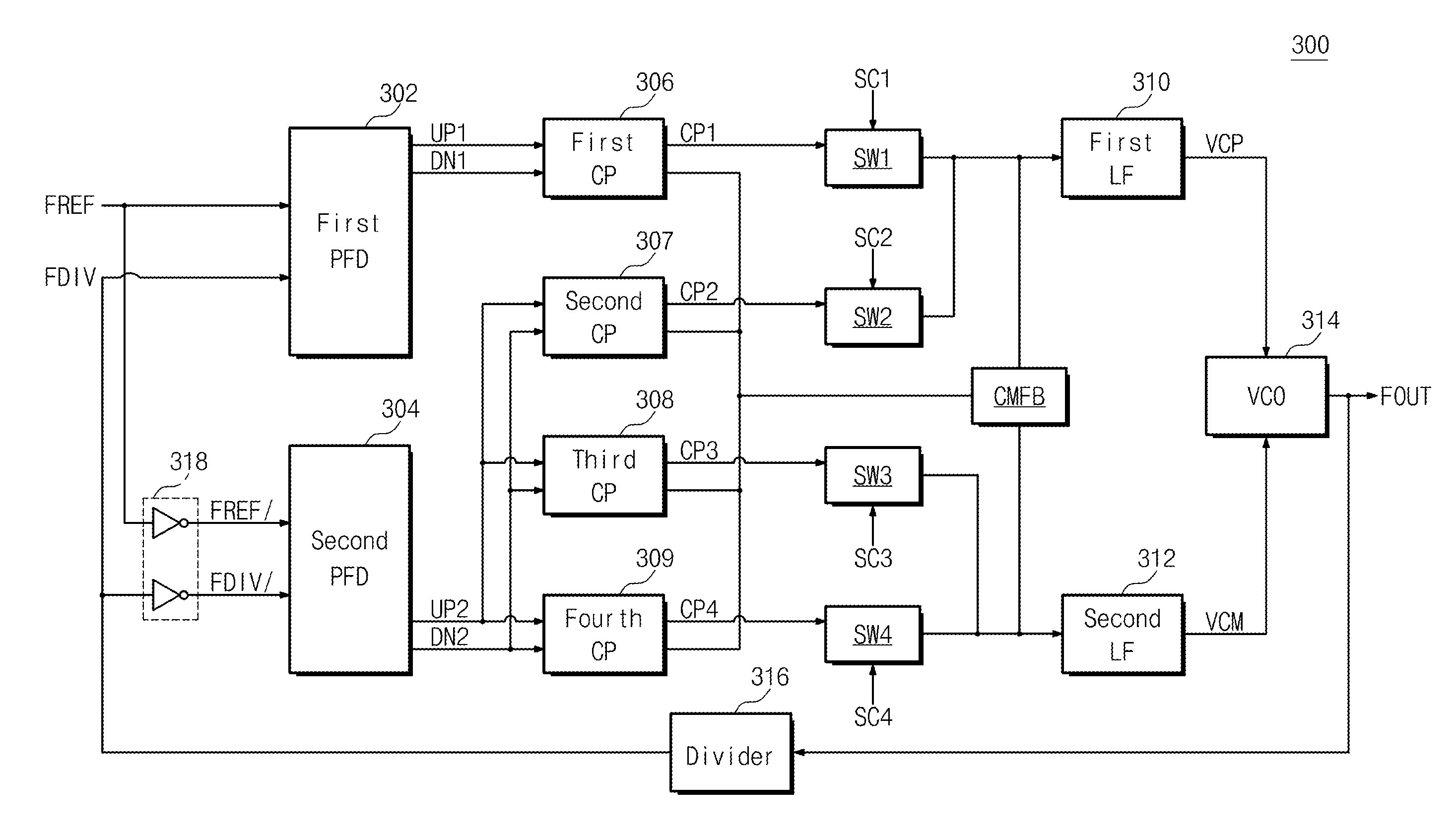
[0057]FIG. 3 is a block diagram schematically illustrating a PLL circuit 200 according to the present invention.

[0058]Referring to FIG. 3, the PLL circuit 200 includes Phase Frequency Detectors (PFDs) 202 and 204, Charge Pumps (CPs) 206 to 209, Loop Filters (LFs) 210 and 212, a Voltage Controlled Oscillator (VCO) 214, a divider 216, a delay circuit 218, a common mode feedback circuit CMFC, and switches SW1 to SW4. Hereinafter, repetitive description on the same elements as those of FIG. 1 will be omitted.

[0059]The first phase frequency detector 202 detects phase and frequency differences between a reference signal FREF and a division signal FDIV.

[0060]Furthermore, the first phase frequency detector 202 outputs a first up signal UP1 and a first down signal DN1 according to the phase and frequency differences between the reference signal FREF and the division signal FDIV.

[0061]The second phase frequency detector 204 detects phase and frequency differences between an inverted reference...


PUM


Abstract

Provided is a PLL circuit driven with a differential controlled voltage. The PLL circuit includes a VCO. The VCO outputs an oscillation signal in response to a difference between first and second control voltages. The PLL circuit includes a first loop for generating the first control voltage, and a second loop for generating the second control voltage having a phase opposite to the first control voltage. Intermediate generated signals of the first loop and intermediate generated signals of the second loop which respectively correspond to the intermediate generated signals of the first loop have opposed phases.

Description

CROSS-REFERENCE TO RELATED APPLICATIONS[0001]This U.S. non-provisional patent application claims priority under 35 U.S.C. §119 of Korean Patent Application No. 10-2010-0125022, filed on Dec. 8, 2010, the entire contents of which are hereby incorporated by reference.BACKGROUND OF THE INVENTION[0002]The present invention disclosed herein relates to a Phase Locked Loop (PLL) circuit, and more particularly, to a PLL circuit which is driven with a differential controlled voltage.[0003]PLL circuits which are used in wired / wireless communication, signal processing and data processing circuits are frequency feedback circuits that generate a signal having an arbitrary frequency in synchronization with a signal having a reference frequency which is inputted from the outside. The PLL circuits are configured for the frequency of an output signal to be controlled according to a phase difference between a reference signal and an output signal. In the PLL circuits, noise characteristics such as co...

Claims


Application Information

Patent Timeline
Patent Type & Authority Applications(United States)
IPC IPC(8): H03L7/087
CPCH03L7/087H03L2207/06H03L7/0893
Inventor YUN, SEOK JU
Owner ELECTRONICS & TELECOMM RES INST