Imaging apparatus

Inactive Publication Date: 2012-06-14
CANON KK
View PDF8 Cites 82 Cited by
  • Summary
  • Abstract
  • Description
  • Claims
  • Application Information

AI Technical Summary

Benefits of technology

[0012]With the foregoing in view, it is an object of the present invention to provide a configuration to divide and image an object using a plurality of image sensors wh

Problems solved by technology

If the entire sample is digitized, however an enormous number of pixels are required, normally several hundred million to several billion.
An advantage of this method is that the joints of the images can be unnoticeable, but a pr

Method used


Image

  • Imaging apparatus
  • Imaging apparatus
  • Imaging apparatus

Examples


first embodiment

Configuration of Imaging Apparatus

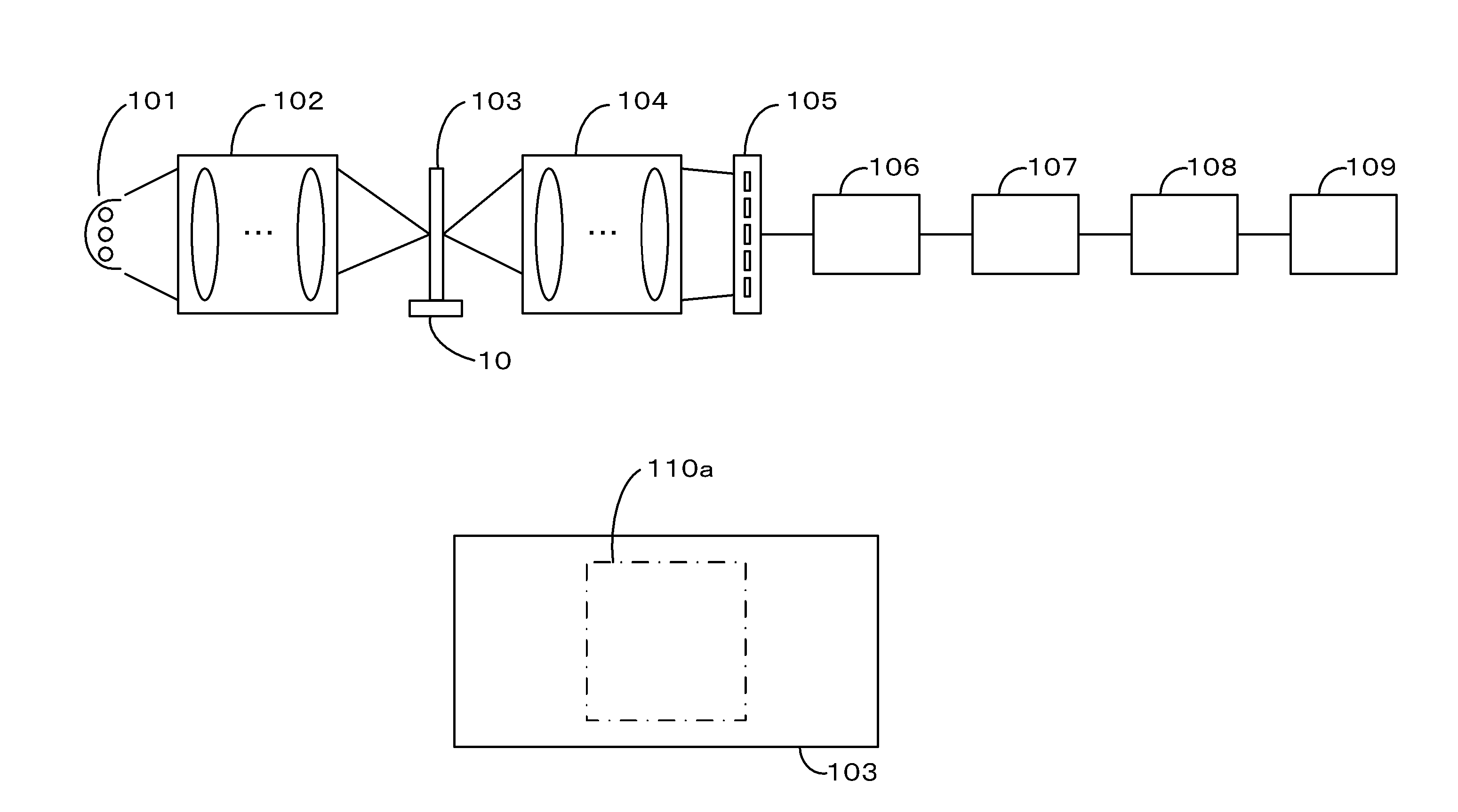
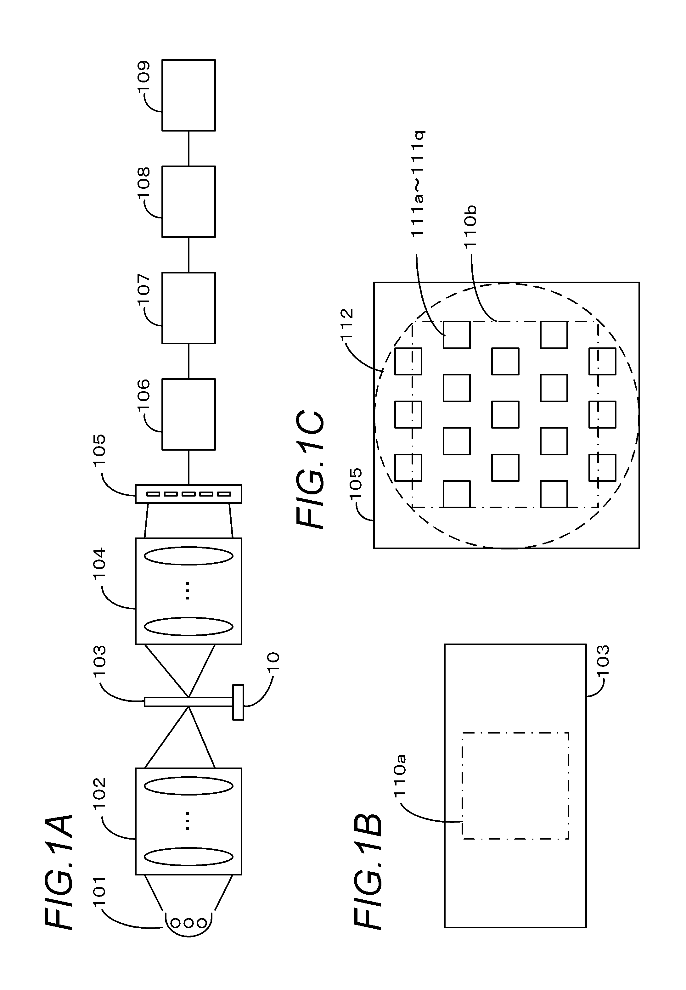
[0033]FIG. 1A to FIG. 1C are schematic diagrams depicting a general configuration related to imaging of an imaging apparatus. This imaging apparatus is an apparatus for acquiring an optical microscopic image of a sample on a slide 103 as a high resolution digital image.

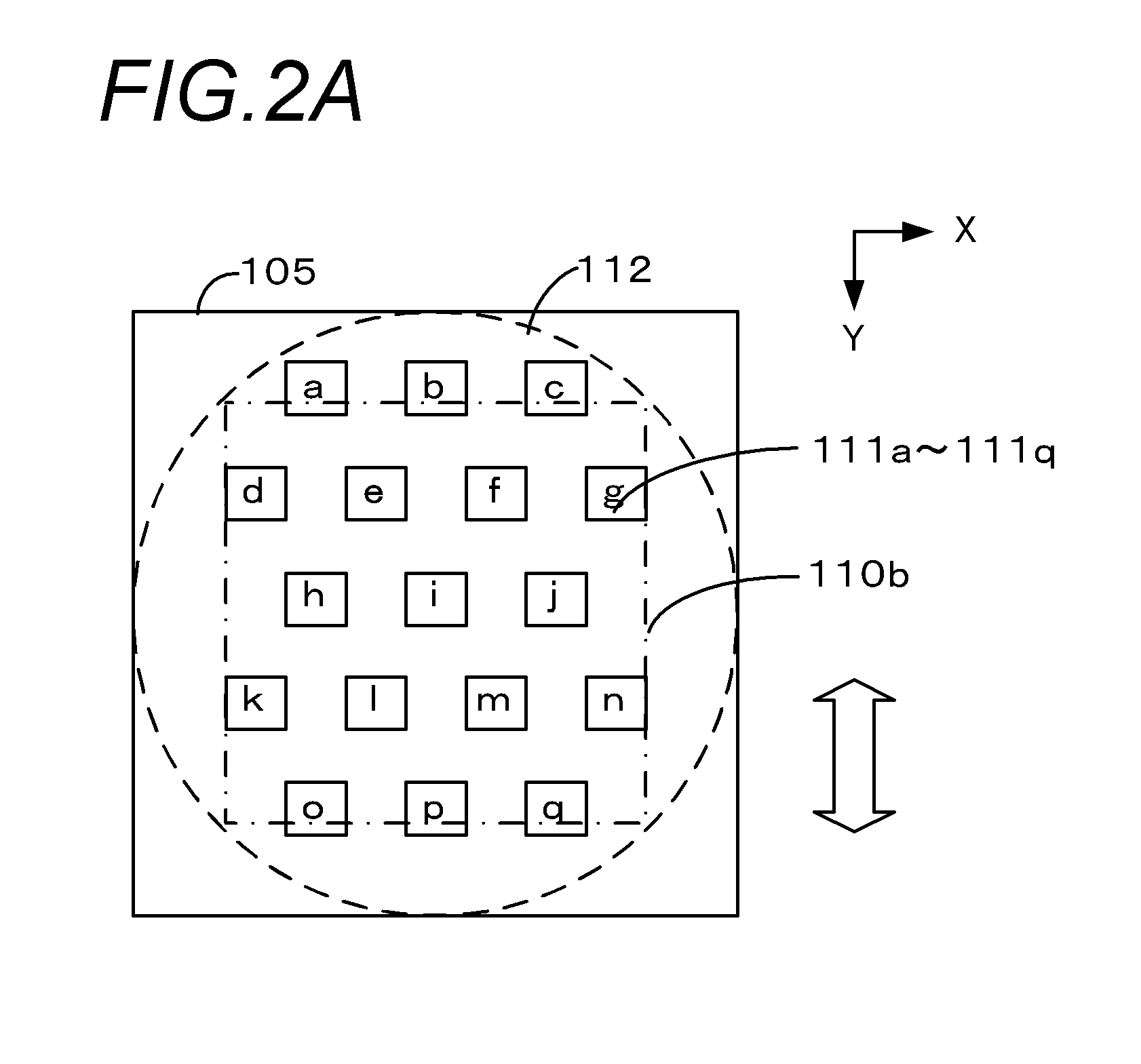
[0034]As FIG. 1A illustrates, the imaging apparatus is comprised of a light source 101, an illumination optical system 102, a moving mechanism 10, an imaging optical system 104, an imaging unit 105, a development / correction unit 106, a merging unit 107, a compression unit 108 and a transmission unit 109. The light source 101 is a means of generating illumination light for imaging, and a light source having emission wavelengths of three colors, RGB, such as an LED (Light Emitting Diode) and an LD (Laser Diode) can be suitably used. The light source 101 and the imaging unit 105 operate synchronously. The light source 101 sequentially emits the lights of RGB, and the imaging unit 105 exp...

second embodiment

[0158]Now the second embodiment of the present invention will be described. In the first embodiment mentioned above, the correction area is determined according to the largest relative coordinate shift amount in the overlapped areas. In other words, the width of the correction area is constant. Whereas in the second embodiment, the correction area is adaptively determined within the overlapped area according to the relative coordinate shift amount of the center line of the overlapped area. Thereby the width of the correction area changes according to the relative coordinate shift amount. Thus the only difference between the present embodiment and the first embodiment mentioned above is the approach to determine the correction area. Therefore in the description of the present embodiment, a detailed description on portions the same as the first embodiment is omitted. For example, the configuration and processing sequence of imaging and image merging of the imaging apparatus shown in F...

third embodiment

[0166]Now the third embodiment of the present invention will be described. In the first embodiment and the second embodiment mentioned above, the method for determining the correction area based on the representative points on the center line of the overlapped area was described. Whereas in the third embodiment, the position of the correction area is adaptively determined based on the correction of two images in the overlapped area. The difference from the first embodiment and the second embodiment is that the calculation of the relative coordinate shift amount does not depend on the center line of the overlapped area. Thus the only difference of the present embodiment from the first and second embodiments is the method for determining the correction area. Therefore in the description of the present embodiment, a detailed description of the portions the same as the first embodiment is omitted. For example, the configuration and the processing sequence of imaging and image merging of...


PUM


Abstract

An imaging apparatus has image sensors, an imaging optical system of which relative position with the image sensors is fixed, and a merging unit which connects images obtained by imaging while changing the relative position between the image sensors and the imaging optical system. Aberration of the imaging optical system in an image obtained by each image sensor is predetermined based on the relative position between the imaging optical system and the image sensor. The merging unit smoothes seams of the two images by setting a correction area in an overlapped area where the two images to be connected overlap with each other, and performing correction processing on pixels in the correction area. A size of the correction area is determined according to the difference in aberrations of the two images, which is determined by a combination of image sensors which have imaged the two images.

Description

BACKGROUND OF THE INVENTION[0001]1. Field of the Invention[0002]The present invention relates to a technology of dividing and imaging an object by using a plurality of image sensors which are discretely arranged, and generating a large sized image by merging the plurality of divided images.[0003]2. Description of the Related Art[0004]In the field of pathology, a virtual slide apparatus is available, where a sample placed on a slide is imaged, and the image is digitized so as to make possible a pathological diagnosis based on a display. This is used instead of an optical microscope, which is another tool used for pathological diagnosis. By digitizing an image for pathological diagnosis using a virtual slide apparatus, a conventional optical microscope image of the sample can be handled as digital data. The expected merits of this are: a quick remote diagnosis, a description of a diagnosis for a patient using digital images, a sharing of rare cases, and making education and practical ...

Claims


Application Information

Patent Timeline
IPC IPC(8): H04N5/217
CPCG06T3/4038G02B21/367H04N5/349H04N5/217H04N23/81H04N25/48
Inventor TAKAYAMA, TOMOHIKO
Owner CANON KK
Why Eureka
Try Eureka