Unlock instant, AI-driven research and patent intelligence for your innovation.

Illuminating device and projection display device using the same

a technology of projection display and illumination device, which is applied in the field of illumination device, can solve the problems of preventing the realization of high polarizing conversion efficiency, difficult to attach the 12 wavelength plate to the second prism, and difficult to miniaturize the illuminating device described in the patent literature 1, etc., and achieves the effect of improving polarizing conversion efficiency and light use efficiency

Inactive Publication Date: 2012-06-14
SHARP NEC DISPLAY SOLUTIONS LTD
View PDF4 Cites 3 Cited by
  • Summary
  • Abstract
  • Description
  • Claims
  • Application Information

AI Technical Summary

Benefits of technology

[0018]The light of the polarized component reflected by the reflective polarizing plate efficiently returns to the surface of the LED. However, on the surface of the LED, only a part of the returned light is reflected toward the polarizing plate. In this way, a light loss occurs on the surface of the LED, thus preventing realization of high polarizing conversion efficiency. For example, it has been reported that polarizing conversion efficiency (gain) is about 1.2 due to the light loss on the surface of the LED.
[0021]It is an object of the present invention to provide a compact illuminating device capable of increasing light use efficiency by improving polarizing conversion efficiency, which can solve the above mentioned problems, and a projection display device that uses the same.Solution to Problems

Problems solved by technology

In this way, a light loss occurs on the surface of the LED, thus preventing realization of high polarizing conversion efficiency.
The illuminating device described in Patent Literature 1 is difficult to be miniaturized because of the use of the PBS polarizing conversion array.
When the first and second prisms are formed at such pitches, it is difficult to attach the ½ wavelength plate to the second prism.
Thus, the problem of miniaturization in the illuminating device that uses the PBS polarizing conversion array will become more prominent.

Method used


Image

  • Illuminating device and projection display device using the same
  • Illuminating device and projection display device using the same
  • Illuminating device and projection display device using the same

Examples


first exemplary embodiment

[0069]FIG. 1 is a schematic view showing a configuration of an illuminating device according to a first exemplary embodiment of the present invention.

[0070]As shown in FIG. 1, the illuminating device according to the present embodiment, which illuminates display element 112 having reflective polarizing plate 111, includes, in addition to reflective polarizing plate 111, light source 101, light guiding rods 102 and 103, illumination lenses 104, 105, 106, 108, and 109, reflecting element 107, and phase plate 110.

[0071]Reflective polarizing plate 111 is, for example, a polarizing plate of a wire-grid type, and configured to transmit, among incident lights, first polarized light (e.g., p-polarized light) while reflecting second polarized light (e.g., s-polarized light) different from the first polarized light in a direction (toward reflecting element 7) opposite an incident direction.

[0072]Display element 112 includes, for example, a liquid crystal panel. For both reflective polarizing ...

second exemplary embodiment

[0137]According to the first exemplary embodiment, as means for causing light enter light guiding rod 103, a set of light source 101 and light guiding rod 102 is used. However, another set of a light source and a light guiding rod can be added. A second exemplary embodiment of the present invention is directed to a case where a plurality of means, each including light sources and light guiding rods, is provided as means for causing light enter light guiding rod 103.

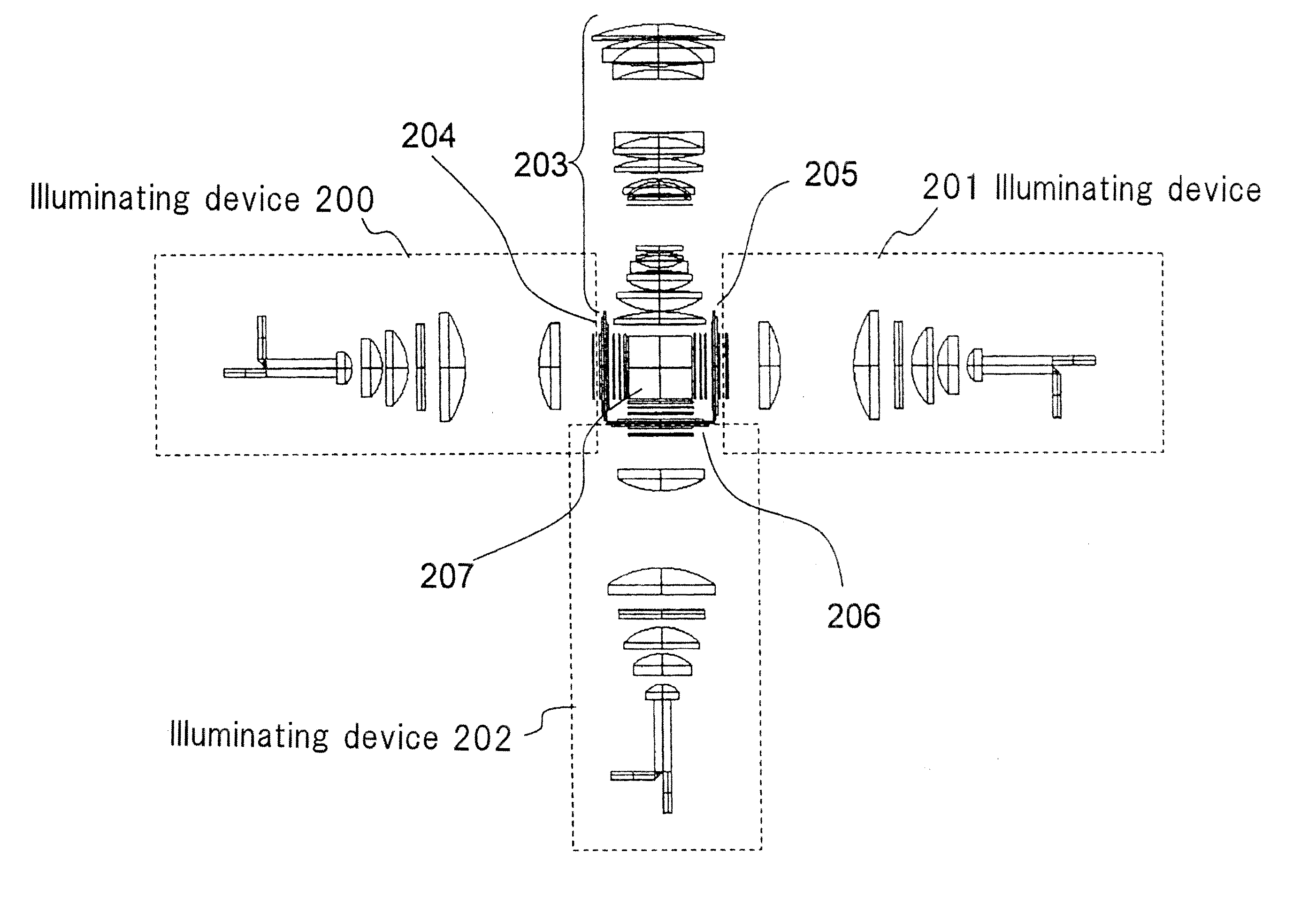
[0138]An illuminating device according to the present embodiment is similar in configuration to that of the first embodiment except for inclusion of two light source means for causing light enter light guiding rod 103. FIG. 11 shows a configuration of the light source means for causing light enter light guiding rod 103.

[0139]As shown in FIG. 11, the illuminating device according to the present embodiment includes two light guiding rods 1101 and 1102 as means for causing light enter light guiding rod 103.

[0140]Light guidin...


PUM


Abstract

Provided is an illuminating device that includes: first light guiding means (3) where light incident from one end surface is propagated inside to exit from the other end surface; illuminating optical system (1) that spatially separates a luminous flux from the other end surface of first light guiding means (3) into a plurality of luminous fluxes, and forms an optical image formed on the other end surface of first light guiding means (3) on display element (12); reflective polarizing plate (11) that is located between illuminating optical system (1) and display element (12), and transmits first polarized light while reflecting second polarized light different that is in polarized state from the first polarized light toward illuminating optical system (1); reflecting element (7) that is disposed at a position where the plurality of luminous fluxes are spatially separated, and that includes transmission regions through which the plurality of luminous fluxes are transmitted, and a reflecting film formed in a region other than the transmission regions to reflect light reflected by reflective polarizing plate (11) toward reflective polarizing plate (11); and phase plate (10) located between reflecting element (7) and reflective polarizing plate (11).

Description

TECHNICAL FIELD[0001]The present invention relates to an illuminating device of a projection display device represented by a liquid crystal projector, and more particularly to an illuminating device that illuminates a display element including a conversion element.BACKGROUND ART[0002]Patent Literatures 1 and 2 discuss a projector that uses a LED (Light Emitting Diode) as a light source for illuminating a DMD (Digital Micromirror Device) serving as a display element (Patent Literatures 1 and 2). The projector of this type is expected to reduce costs more than a projector that uses a white discharge lamp, and achieve performance including miniaturization, lower power consumption, and a wider color reproduction range.[0003]There are also a projector that uses a single LCoS (Liquid Crystal on Silicon) element (Nonpatent Literature 1), and a projector that users three liquid crystal panels as display elements (Nonpatent Literatures 2 and 3).[0004]In the liquid crystal projector, usually,...

Claims


Application Information

Patent Timeline
IPC IPC(8): G03B21/14F21V9/14
CPCG03B21/2073G03B21/14
Inventor KATOU, ATSUSHI
Owner SHARP NEC DISPLAY SOLUTIONS LTD