Optical biosensor with focusing optics

a biosensor and optical technology, applied in the field of optical biosensor focusing optics, can solve the problems of complex optical systems, increased field of view, image deterioration at the periphery of imaged area, etc., and achieve the effect of accurate image, large investigation area, and elongated shape of investigation region

Active Publication Date: 2012-06-14
SIEMENS HEALTHINEERS NEDERLAND BV
View PDF12 Cites 13 Cited by
  • Summary
  • Abstract
  • Description
  • Claims
  • Application Information

AI Technical Summary

Benefits of technology

[0014]The focusing optics, the optical bio sensor, and the method according to the above aspects of the invention have in common to allow the focusing of several sub-beams of a large parallel output light beam onto different zones of a detector plane. An output light beam with a large diameter can hence be processed while at the same time optical distortions in peripheral areas are avoided because processing is done with respect to sub-beams of limited extension. This allows to survey a comparatively large investigation region of an optical bio sensor with a high accuracy of the optical measurements but without a complex optical system that might be difficult to adjust. Instead, the focusing optics comprising a plurality of lenslets arranged adjacent to each other suffices.
[0019]The investigation region may preferably cover a plurality of physically separated sample chambers, called “wells”, that can separately provide samples. Such wells may for example be realized on the surface of a (transparent) carrier. The provision of separated wells allows to prepare one or more samples under different conditions and to evaluate these preparations in parallel. The plurality of separated wells typically implies a comparatively large, elongated shape of the investigation region. Nevertheless, this investigation region can accurately be imaged onto the detector plane with the help of the focusing optics.

Problems solved by technology

This increases the field of view that has to be surveyed, leading either to image deteriorations at the periphery of the imaged area or to complex optical systems.

Method used


Image

  • Optical biosensor with focusing optics
  • Optical biosensor with focusing optics
  • Optical biosensor with focusing optics

Examples


Embodiment Construction

[0036]Though the present invention will in the following be described with respect to a particular setup (using magnetic particles and frustrated total internal reflection as measurement principle), it is not limited to such an approach and can favorably be used in many different applications and setups.

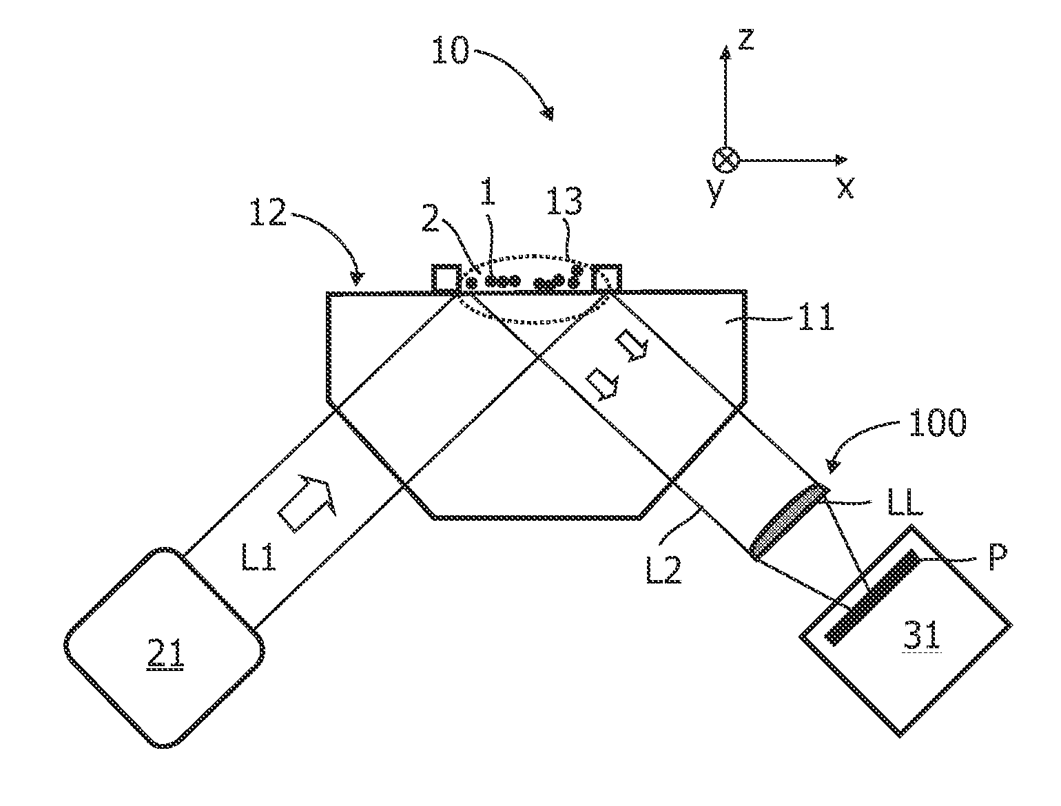
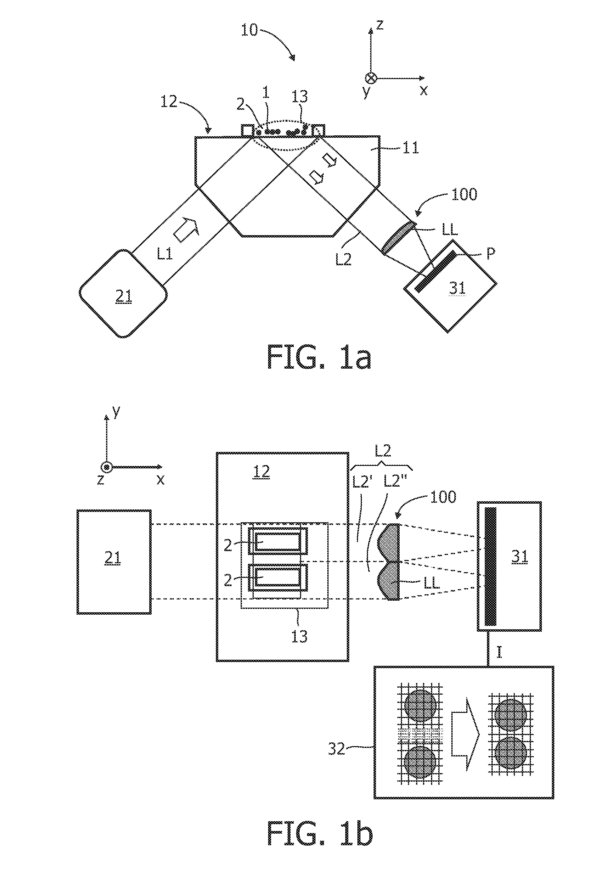
[0037]FIGS. 1a and 1b show a general setup with of an optical biosensor 10 according to the present invention in a side view and a top view, respectively. The biosensor 10 setup comprises a carrier 11 that may for example be made from glass or transparent plastic like polystyrene. The carrier 11 comprises on its upper “contact surface”12 a plurality of physically separated sample chambers or wells 2 in which sample fluids with target components to be detected (e.g. drugs, antibodies, DNA, etc.) can be provided. The samples further comprise magnetic particles, for example superparamagnetic beads, wherein these particles are usually bound (via e.g. a coating with antibodies) as labels ...


PUM

PropertyMeasurementUnit
refractive indexaaaaaaaaaa

Abstract

The invention relates to focusing optics (100) for a biosensor (10) which allow with simple means to accurately image an extended investigation region (13) onto a detector plane (P). To this end, the focusing optics (100) comprises at least two focusing lenslets (LL) that are arranged adjacent to each other such that they image an incident parallel light beam (L2) that is directed along a main optical axis (MOA) onto a common plane (P). The output light beam (L2) that is received by the focusing optics (100) may preferably originate from total internal reflection of a parallel input light beam (L1) at the investigation region (13) of a transparent carrier.

Description

FIELD OF THE INVENTION[0001]The invention relates to focusing optics for an optical biosensor, to a biosensor comprising such optics, and to a method for imaging an investigation region onto the detector plane of a light detector.BACKGROUND OF THE INVENTION[0002]The WO 2008 / 155716 discloses an optical biosensor in which an input light beam is totally internally reflected and the resulting output light beam is detected and evaluated with respect to the amount of target components at the reflection surface. When a plurality of analytes shall be tested in parallel in such or a similar biosensor, it is often necessary to provide the sample in spatially separated chambers. This increases the field of view that has to be surveyed, leading either to image deteriorations at the periphery of the imaged area or to complex optical systems.SUMMARY OF THE INVENTION[0003]Based on this situation it was an object of the present invention to provide means that allow the simultaneous detection of ana...

Claims


Application Information

Patent Timeline
Patent Type & Authority Applications(United States)
IPC IPC(8): G01N21/55G02B3/00
CPCG01N21/552G01N21/648G02B27/126G02B3/0068G02B27/1066G01N2201/0638
Inventor SCHLEIPEN, JOHANNES JOSEPH HUBERTINA BARBARABRULS, DOMINIQUE MARIA
Owner SIEMENS HEALTHINEERS NEDERLAND BV
Why Eureka
Try Eureka