However, still orthogonal resource blocks have to be used for the transmission and reception from the relays.
The main obstacle to FD implementation is the lack of availability of practical designs rather than any inherent physical limitation.
However, several factors affect the implementation of such a solution.
Second, the received signals have traveled through the air (from another terminal) and are attenuated at least as much as the free-space loss.
Thus, exact
recreation of the signal intended to be received at the
receiver (we will refer to this as the “intended receive signal” from now on) might not be possible or very hard.
Third, what aggravates the problem even more is the
power ratio between the locally transmitted signal (which is self interfering) and the received signal, which is usually large (ie, the locally transmitted signal power could be several orders of magnitudes larger than the received signal power).
Therefore, even a slight deviation in the device functions of the devices that are used to subtract the locally transmitted (self interfering) signal from the received signal, would result in a considerable residue of the interfering signal power to leak and remain combined with the received signal; this may
mask out the intended receive signal, completely.
However, the
digitization noise would be more or at least comparable with the intended receive signal which could make the
recovery of this signal impossible.
This problem is somewhat similar to the reception problem in
satellite communications where the received signal is usually very close to the
noise floor.
In this case, even with HD transmission, it becomes hard to identify the intended receive signal.
While the first FD
system by one person relied on a specific antenna cancellation technique to achieve a significant portion of self-interference cancellation, the various limitations of this technique prompted latter works to move away from antenna cancellation and rely on analog cancellation achieved through channel
estimation.
This not only adds complexity to the overall
system but also makes the performance sensitive to wide-band channels.
More importantly, none of the existing FD schemes can be readily scaled to
MIMO systems where the nodes have more than two antennas.
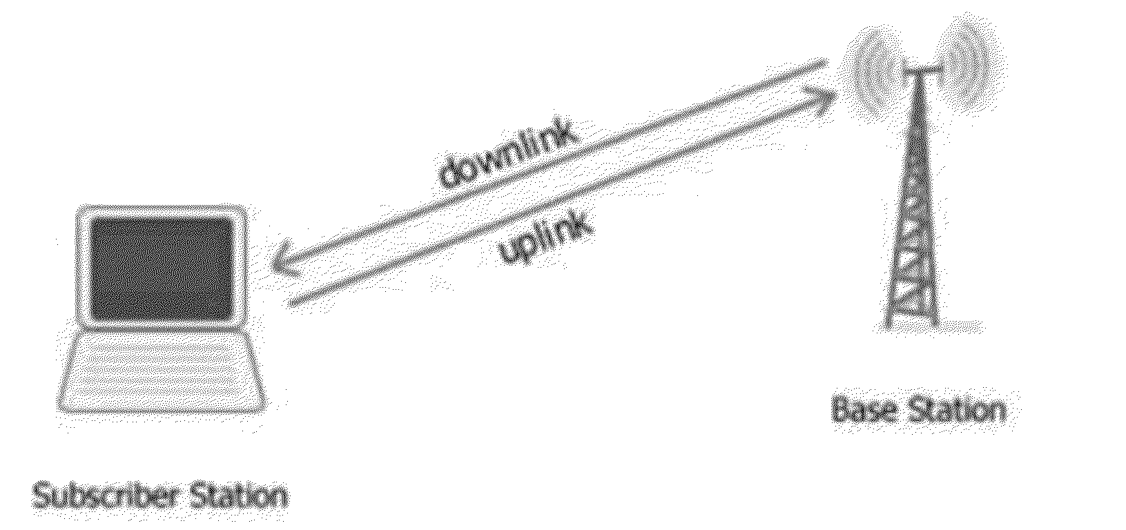
In half-duplex systems we either receive or transmit in time TDD or in frequency FDD, so it may be thought that we waste half of the resources.
The main challenge of the full duplex communication is to cancel the
self interference that is orders of magnitude stronger than the received signal from the intended transmitters.
However this interference is partly known due to the fact that the
transmitter exactly knows its own transmitted signal however the exact channel between the transmit and receive antennas at the
base station is not known.
The key challenge in realizing such a device lies in addressing the self-interference generated by the Tx antenna at the Rx antenna.
A Tx-Rx antenna separation of about 6-8 inches results in a
path loss of about 40
dBm (depending on channel characteristics), resulting in a self-interference of at least −20
dBm.
While one can solely employ digital interference cancellation techniques, current ADC's do not have a resolution to pass a received signal which is 73 dB less than the
noise floor.
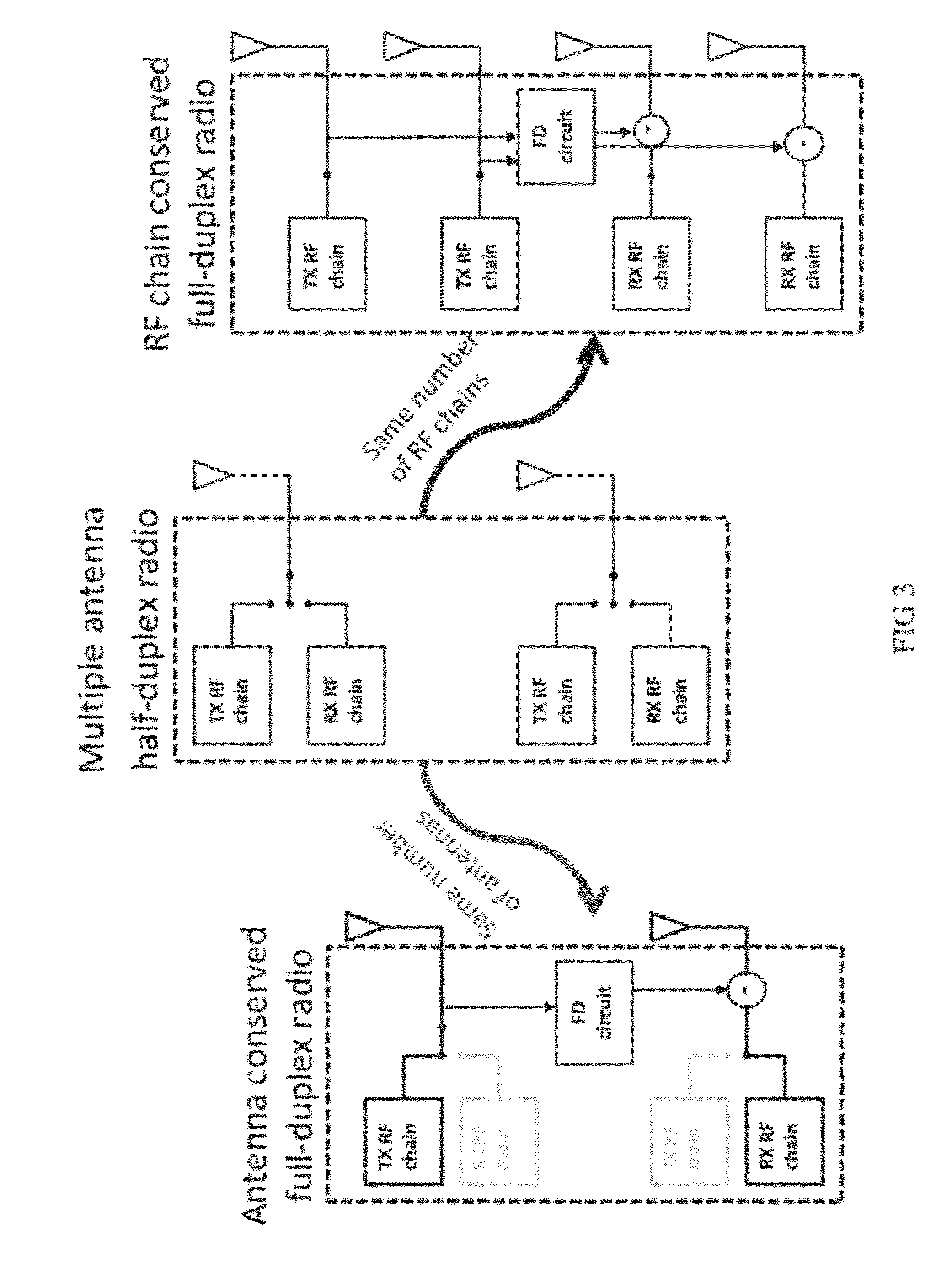
Three limitations of such an antenna cancellation approach were pointed out in previous works: (i) the dependence on λ allows for maximum cancellation only at the
center frequency, with performance degrading for frequencies away from the center—a problem for
wideband systems; (ii) employing an additional antenna may not justify the gains compared to a 3×3
MIMO system, and (iii) due to asymmetric antenna placement, manual tuning of amplitude and phase of the closer Tx antenna is required to achieve a null, which prevents real-time operation.
The first limitation is that the design required the placement of one of the Tx antennas at a distance d+λ / 2 which then depends on the bandwidth and thus leading to maximum cancellation only at the
center frequency (and hence not efficient for
wideband signals).
The second limitation is that the design requires an extra antenna which may not be justifiable compared to a 3×3
MIMO system.
The third limitation is that the design requires manual tuning of variable attenuators and phase shifters to compensate for channel changes (even if channels between the two Tx antennas and the Rx antenna are symmetric, the channels will still change with time); such requirement is primarily due to the use of asymmetric positioning of the antennas (see the first limitation above) and thus disappears when antennas are symmetrically placed.
One other limitation Applicant sees with antenna cancellation using asymmetric placement antennas is that it is not apparent how it can scale to
MIMO systems.
However, such a design encounters the following limitation.
This not only makes the design complicated but also the performance quite sensitive to wide-band channels.
Applicants observe that existing antenna cancellation and analog cancellation approaches cannot be readily extended to
MIMO systems.
However, such an antenna placement cannot be realized for a MIMO system using the prior approach.
This in turn results in the use of N2 variable delays and attenuators, each of which has to be auto tuned and adapted to track the N2 self-interference channels, which seems practically infeasible.

