This helps you quickly interpret patents by identifying the three key elements:
Problems solved by technology
Method used
Benefits of technology
Benefits of technology
[0057]According to a communication device of the present invention, low power consumption and real time performance of the communication terminal devices may be achieved at the same time even in applications such as peak suppression with no regularity of data.
Problems solved by technology
However, while the low power consumption of the terminal device 1002 may be achieved, the buffering time in the control station 1001 increases, and thus the delay time until the data is delivered to the terminal device 1002 increases.
This presents a problem for application for which real time performance and immediacy are demanded.
Method used
Image
Click on the blue label to locate the original text in one second.
Reading with bidirectional positioning of images and text.
Examples
embodiment 1
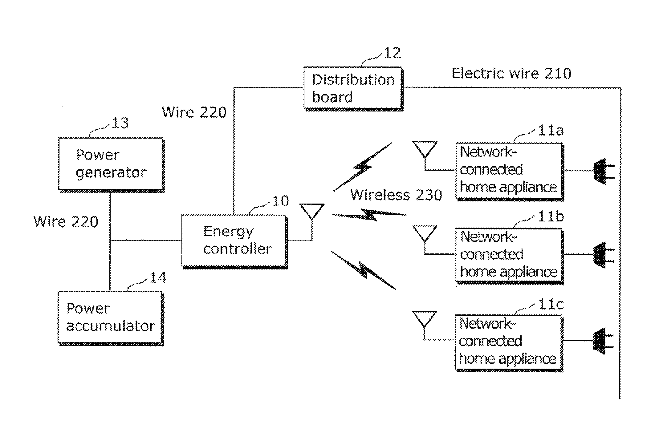
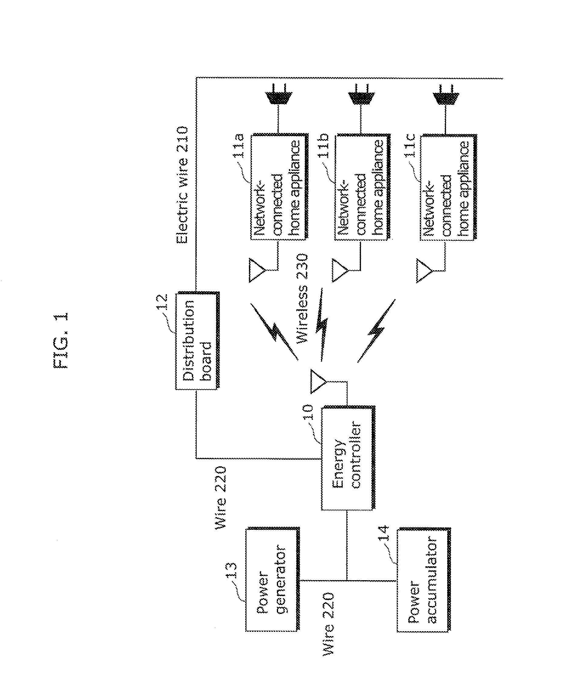
[0107]FIG. 1 is a diagram showing an example of a network configuration of Embodiment 1 of the present invention.
[0108]In FIG. 1, an energy controller 10 is connected to network-connected home appliances 11a, 11b, 11c by a wireless 230. The energy controller 10 is included in “communication device” described in the accompanying claims, and the network-connected home appliances 11a, 11b, 11c are included in “communication terminal device” described in the accompanying claims.
[0109]The wireless 230 may be a connection according to a specific low power wireless which conforms to, for example, the IEEE 802.15.4 standard, the IEEE 802.11 standard, or ARIB (Association of Radio Industries and Businesses).
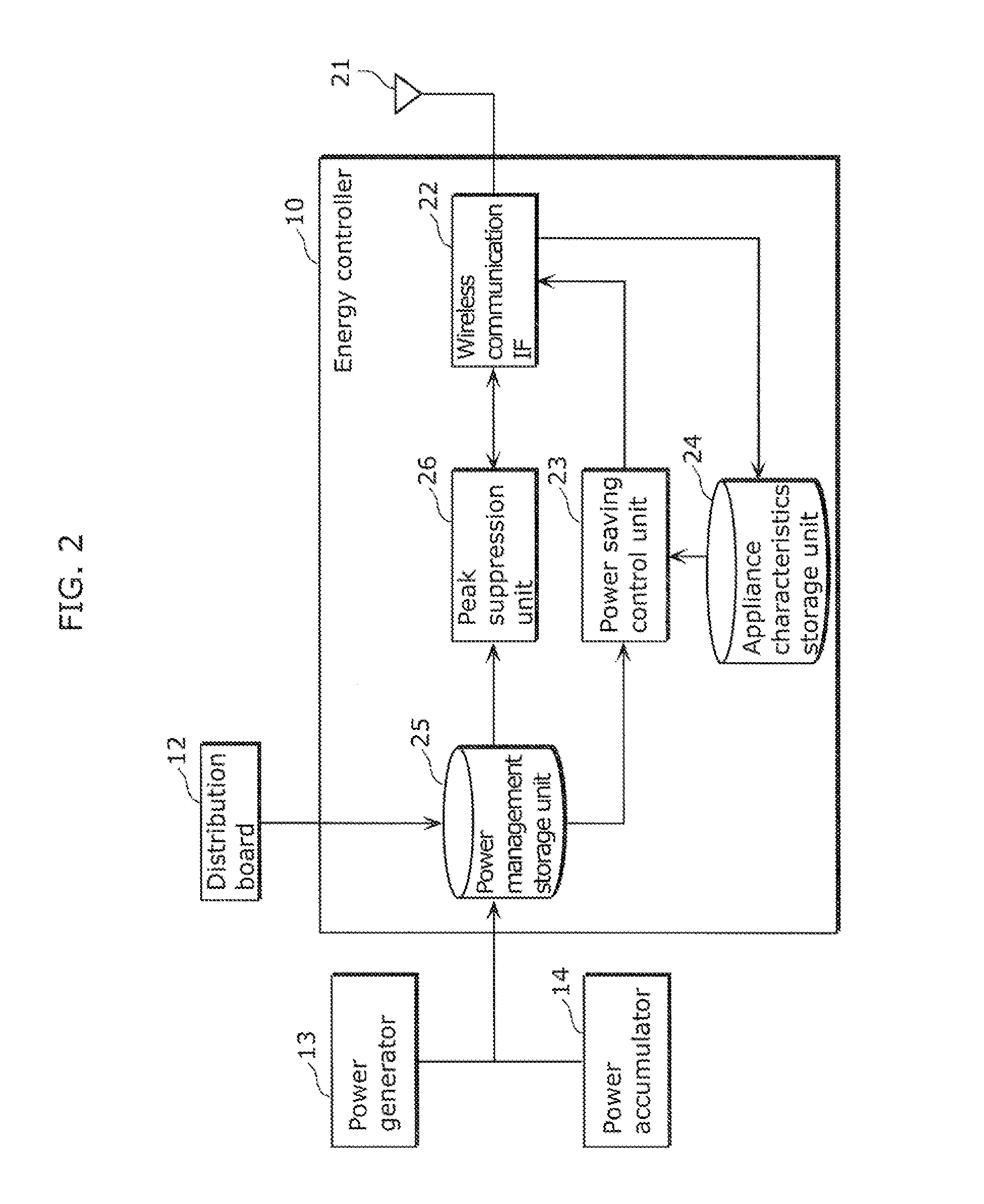
[0110]A distribution board 12 supplies power to all the electric appliances (for example, network-connected home appliance 11a) in a house via an electric wire 210, and can measure the total power consumption in the house. The distribution board 12 is connected to the energy controller 10...
embodiment 2
[0206]In the above-described Embodiment 1, a beacon period is calculated based on the power value difference between the available power supply value and the total power consumption value, and the characteristics of the rate of change in the power consumption of the home appliances, and then the beacon period is controlled. Consequently, when the power value difference has a large margin for peak suppression, a longer beacon period is set, and thus low power consumption is achieved, while when the power value difference has a small margin for peak suppression, a shorter beacon period is set, and thus a request for peak suppression can be immediately processed.
[0207]On the other hand, in the present Embodiment 2, after a beacon period is calculated, the beacon period is compared with the beacon value in the stored beacon table and then final beacon period is determined. Consequently, the beacon period can be dynamically changed in a system in which the beacon period is defined by sev...
embodiment 3
[0226]In the above-described Embodiment 1, a beacon period is calculated based on the power value difference between the available power supply value and the total power consumption value, and the characteristics of the rate of change in the power consumption of the home appliances, and then the beacon period is controlled. Consequently, when the power value difference has a large margin for peak suppression, a longer beacon period is set, and thus low power consumption is achieved, while when the power value difference has a small margin for peak suppression, a shorter beacon period is set, and thus a request for peak suppression can be immediately processed.
[0227]On the other hand, in the present Embodiment 3, after a beacon period is calculated, the beacon period is compared with allowable delay times for the applications which are utilized in the wireless network system, and then final beacon period is determined. Consequently, setting of a beacon period exceeding the allowable ...
PUM
Abstract
An energy controller (10) as a communication device for transmitting and receiving data by transmitting a signal for establishing transmission and reception of the data to network-connected home appliances (11a to 11c), the energy controller (10) including: a power savingcontrol unit which determines a transmission period such that the transmission period during which the signal is transmitted is increased as a power value difference increases, which is a value obtained by subtracting the total power consumption value of a power consumption appliance from available power supply value to the power consumption appliance including the network-connected home appliances (11a to 11c); and wireless communication IF (22) for transmitting the signal containing the information indicating the transmission period to the network-connected home appliances (11a to 11c) in order to set the network-connected home appliances (11a to 11c) in an active state with a period according to the transmission period.
Description
TECHNICAL FIELD[0001]The present invention relates to a communication device and a communication method in a wireless network system such as WLAN (WirelessLocal Area Network) of IEEE (Institute of Electrical and Electronics Engineers) 802.11 standard, or WPAN (WirelessPersonal Area Network) of EEE 802.15 standard.BACKGROUND ART[0002]In recent years, attention is being focused on a network shared by wireless terminals with low power consumption, such as WPAN or a sensor network. As a system like system, there is a system called Active RF (Radio Frequency) which sends a radio signal itself.[0003]FIG. 43 is a diagram showing an example of a conventional wireless network configuration.[0004]In FIG. 43, the wireless network includes a control station 1001 which is a wireless controlstation, and terminal devices 1002, 1003, 1004 which are a plurality of wireless terminal devices. The control station 1001 periodically broadcasts a beacon packet including control information to the termi...
Claims
Application Information
Patent Timeline
Application Date:The date an application was filed.
Publication Date:The date a patent or application was officially published.
First Publication Date:The earliest publication date of a patent with the same application number.
Issue Date:Publication date of the patent grant document.
PCT Entry Date:The Entry date of PCT National Phase.
Estimated Expiry Date:The statutory expiry date of a patent right according to the Patent Law, and it is the longest term of protection that the patent right can achieve without the termination of the patent right due to other reasons(Term extension factor has been taken into account ).
Invalid Date:Actual expiry date is based on effective date or publication date of legal transaction data of invalid patent.

