Radiation scanning and disabling of hazardous targets in containers

a technology for hazardous targets and containers, applied in material analysis, material analysis using wave/particle radiation, nuclear engineering, etc., can solve the problems of electrical components such as semiconductor devices, susceptible to damage and/or destruction from radiation, and achieve the effect of prolonging storage and stopping sprouting

Active Publication Date: 2012-06-14
VAREX IMAGING CORP
View PDF0 Cites 8 Cited by
  • Summary
  • Abstract
  • Description
  • Claims
  • Application Information

AI Technical Summary

Benefits of technology

[0014]Electrons and photons have been used for many years to cross link materials and to sterilize medical components. For example, food products have been treated with radiation to kill bacteria, fungi, and pests. Radiation has also been used to stop sprouting and other negative effects from the prolonged storage of food products. The energies used in such applications range from about a few keV to about 10 MeV for electrons and from about 50 keV to about 10 MeV for photons. Radioactive materials, such as Cesium-137 (137Cs) and Cobalt-60 (60Co), have been used extensively for cross linking and the sterilization of medical goods. Electron systems have been used to clean flue gases from power plants and to treat water and chemical waste streams. Additionally, studies have been done using 60Co to treat water that has been provided to municipal drinking supplies. It is also known that electronics, such as semiconductor devices, are susceptible to damage and / or destruction from radiation. For this reason, electronics employed on satellites typically include extensive shielding, insulation, and redundancies, for example, as discussed in U.S. Pat. No. 6,511,893, U.S. Pat. No. 6,650,003 and U.S. Pat. No. 7,071,749, which are incorporated by reference herein. The military has studied the use of intense bursts of radiation to damage sensitive communication electronics in satellites and communication systems.

Problems solved by technology

It is also known that electronics, such as semiconductor devices, are susceptible to damage and / or destruction from radiation.

Method used


Image

  • Radiation scanning and disabling of hazardous targets in containers
  • Radiation scanning and disabling of hazardous targets in containers
  • Radiation scanning and disabling of hazardous targets in containers

Examples


Embodiment Construction

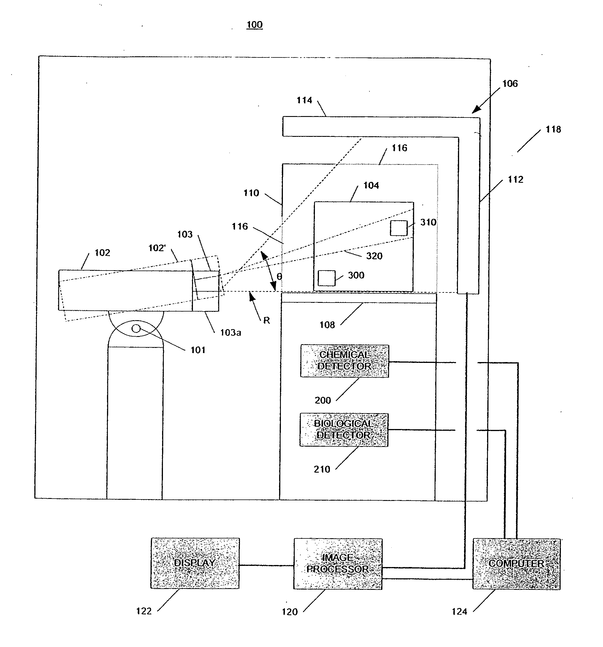
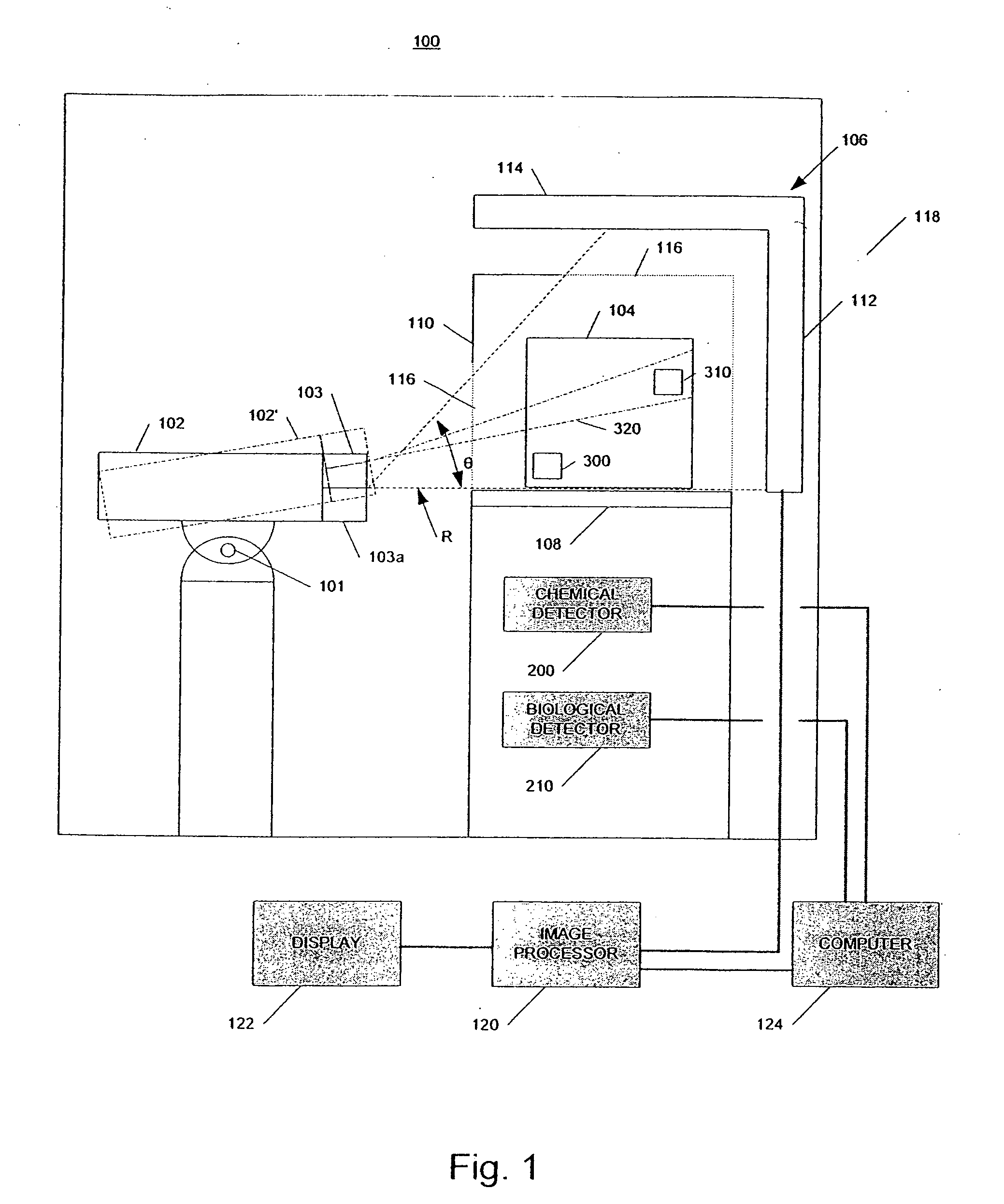
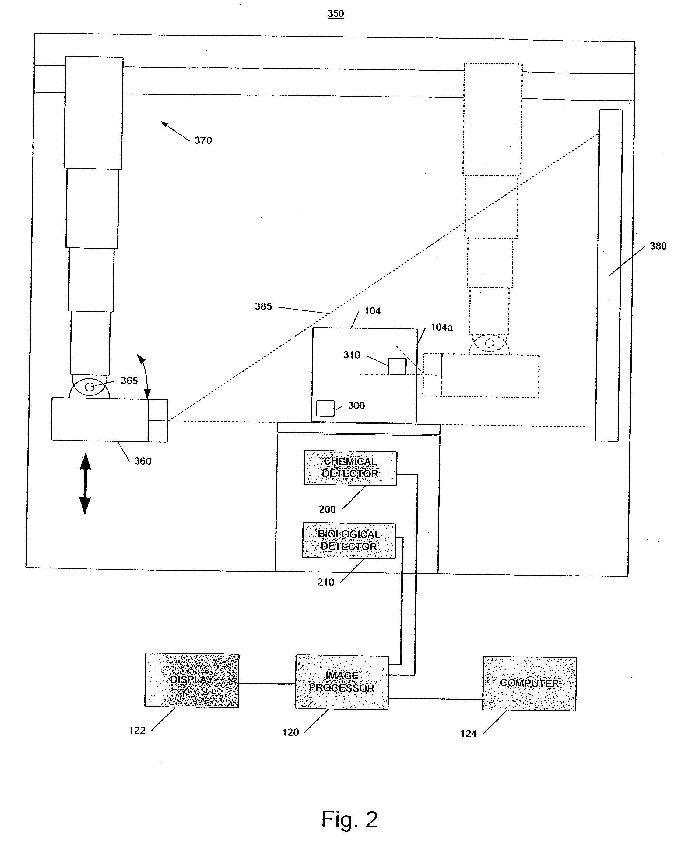
[0028]In accordance with embodiments of the invention, a system and method identifies a potential threat or hazardous object in a container, such as a cargo conveyance, and disables the potential threat in whole or in part using radiation from a radiation source. As used herein, the term “radiation” is meant to include, but should not be limited to, beams of electrons, X-ray radiation, gamma ray radiation and neutrons. In some embodiments, the system uses radiation scanning, such as X-ray scanning, chemical detectors, and / or biological detectors to identify at least a potential presence of high atomic number material or high density material, that could be special nuclear material (“SNM”) or shielding for SNM, chemical agents, and / or biological agents. Although not required, the same high energy radiation source used in scanning the container may be used to disable the potential threat.

[0029]FIG. 1 is a schematic representation of an example of a radiation inspection / disabling syste...


PUM

PropertyMeasurementUnit
energyaaaaaaaaaa
widthaaaaaaaaaa
lengthaaaaaaaaaa

Abstract

In one example, a method of examining a container is disclosed comprising detecting a potential threat within contents of a container using radiation scanning and disabling the potential threat with radiation. In another example, a method of examining a container is disclosed comprising scanning at least a portion of the container with a first radiation beam, detecting radiation interacting with contents of the container, identifying a potential threat contained based, at least in part, on the detected radiation, and disabling the potential threat with a dose of radiation from a second radiation beam. The potential threat may be a nuclear, chemical, and/or biological weapon, for example. Chemical and/or biological detectors may also be provided. The threat and/or electronics associated with the threat, may be disabled. Systems are also disclosed.

Description

FIELD OF THE INVENTION[0001]Radiation scanning of objects, including large objects such as cargo containers, to identify hazardous targets and to disable or render harmless the identified targets.BACKGROUND OF THE INVENTION[0002]Radiation is commonly used in the non-invasive inspection of contents of objects, such as luggage, bags, briefcases, cargo containers, and the like, to identify hidden contraband at airports, seaports, and public buildings, for example. The contraband may include hidden guns, knives, explosive devices and materials, illegal drugs, and a nuclear or a “dirty” radioactive bomb, for example. One common inspection system is a line scanner, where the object to be inspected is passed between a stationary source of radiation, such as a gamma ray radiation or X-ray radiation, and a stationary detector. The transmitted radiation is detected and measured. Radiographic images of the contents of the object may be generated for inspection. The images show the shape, size ...

Claims


Application Information

Patent Timeline
Patent Type & Authority Applications(United States)
IPC IPC(8): G01N23/04
CPCG01V5/0016
Inventor JOHNSON, JAMES H.CLAYTON, JAMES E.
Owner VAREX IMAGING CORP
Why Eureka
Try Eureka