Ball joint

Inactive Publication Date: 2012-06-14
SHIMAZAWA TOSHIHIRO
View PDF10 Cites 9 Cited by
  • Summary
  • Abstract
  • Description
  • Claims
  • Application Information

AI Technical Summary

Benefits of technology

[0010]According to the present invention, the small-diameter opening of the dust cover can be reliably retained with the ball stud since the ball stud is provided with the first flange part and the second flange part. Therefore, the close contact of the dust cover with respect to the ball stud can be maintained even when the elastic force of the dust cover is changed depending on a used environment, and the film is not required to have an increased thickness or have a complex shape in order to ensure the urging force of the dust cover toward the ball stud in that process. Therefore, a ball joint capable of maintaining a good sealing characteristic can be provided at low cost. According to the present invention, the dust cover is provided with the protruding part having a gap at least at one location and abutting the spherical-head-part side end surface of the second flange part of the ball stud. Therefore, the inner peripheral part of the dust cover can be reliably positioned between the first flange part and the second flange part of the ball stud. Therefore, a good sealing characteristic can be ensured. Moreover, the protruding part is provided with the location not abutting the spherical-head-part side end surface of the second flange part of the ball stud. As a result, the deformation rigidity of the protruding part can be reduced. Therefore, upon assembly of the dust cover, stoppage in the state in which the protruding part is spread over the outer peripheral surface of the second flange part is not caused, and the dust cover can be easily assembled at a predetermined position. Furthermore, in the state in which the ball joint is used, the protruding part is provided with a part that is not in contact with the ball stud when the ball stud actuates to slide about the axial line thereof with respect to the socket. Therefore, joined-turning of the dust cover and the ball stud can be preve

Problems solved by technology

Therefore, in the conventional ball joint as described above, the urging force of the small-diameter side end part with respect to the flange-part end surface is reduced along with reduction in the elastic force of the dust cover, and the close contact between the small-diameter side end part and the flange part cannot be maintained.
Therefore, an appropriate assembly state with respect to the ball stud cannot be maintained, and the sealing characteristic of the dust cover is reduced.
Therefore, the structure of the ball joint described in Patent Literature 1 has a problem that the dust cover cannot exhibit a good sealing characteristic in all the environments in which the ball joint is used.
However, the larger the film length, the less the film part of the dust cover

Method used


Image

  • Ball joint
  • Ball joint
  • Ball joint

Examples


Embodiment Construction

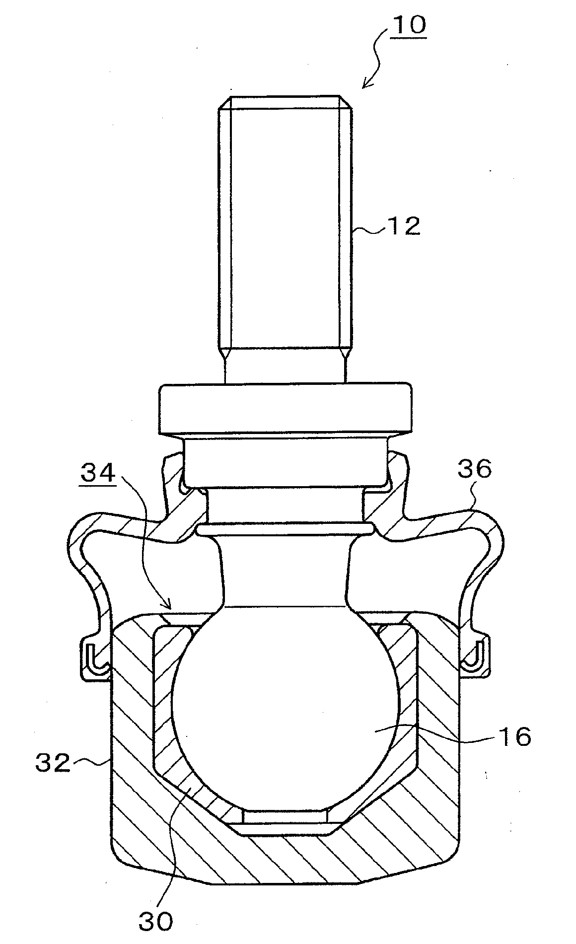
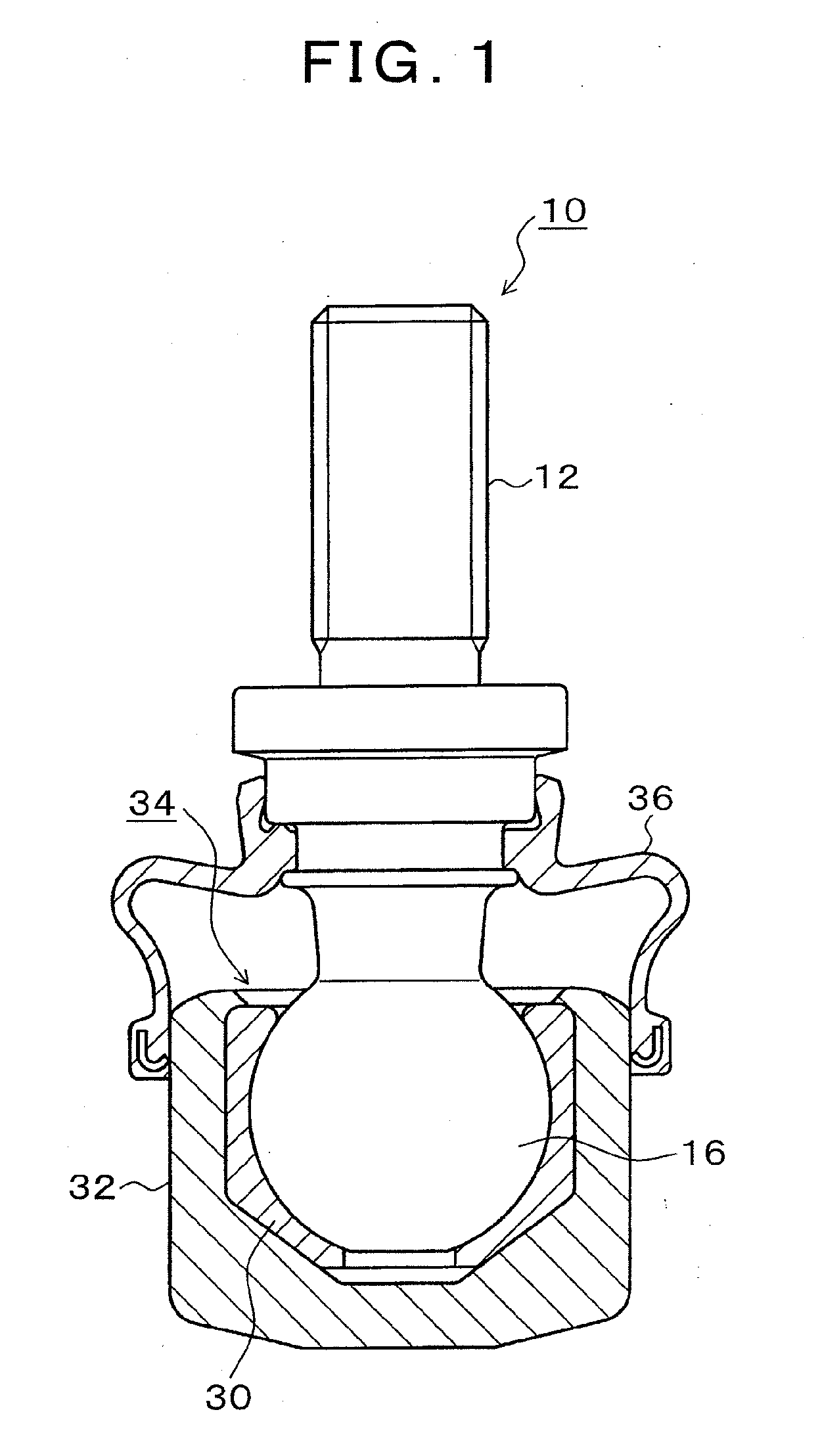
[0021]FIG. 1 is a cross-sectional view showing an embodiment of a ball joint of the present invention. In FIG. 1, the ball joint 10 is composed of a ball stud 12, a ball seat 30, a socket 32, and a dust cover 36. In the ball joint 10, a spherical head part 16 formed at an end of the ball stud 12 is incorporated into the socket 32 via the ball seat 30, and an opening 34 of the socket 32 is subjected to caulking to swingably and turnably support the ball stud 12. The dust cover 36, which prevents water and dust from entering the inside from the opening 34, is attached between the ball stud 12 and the socket 32.

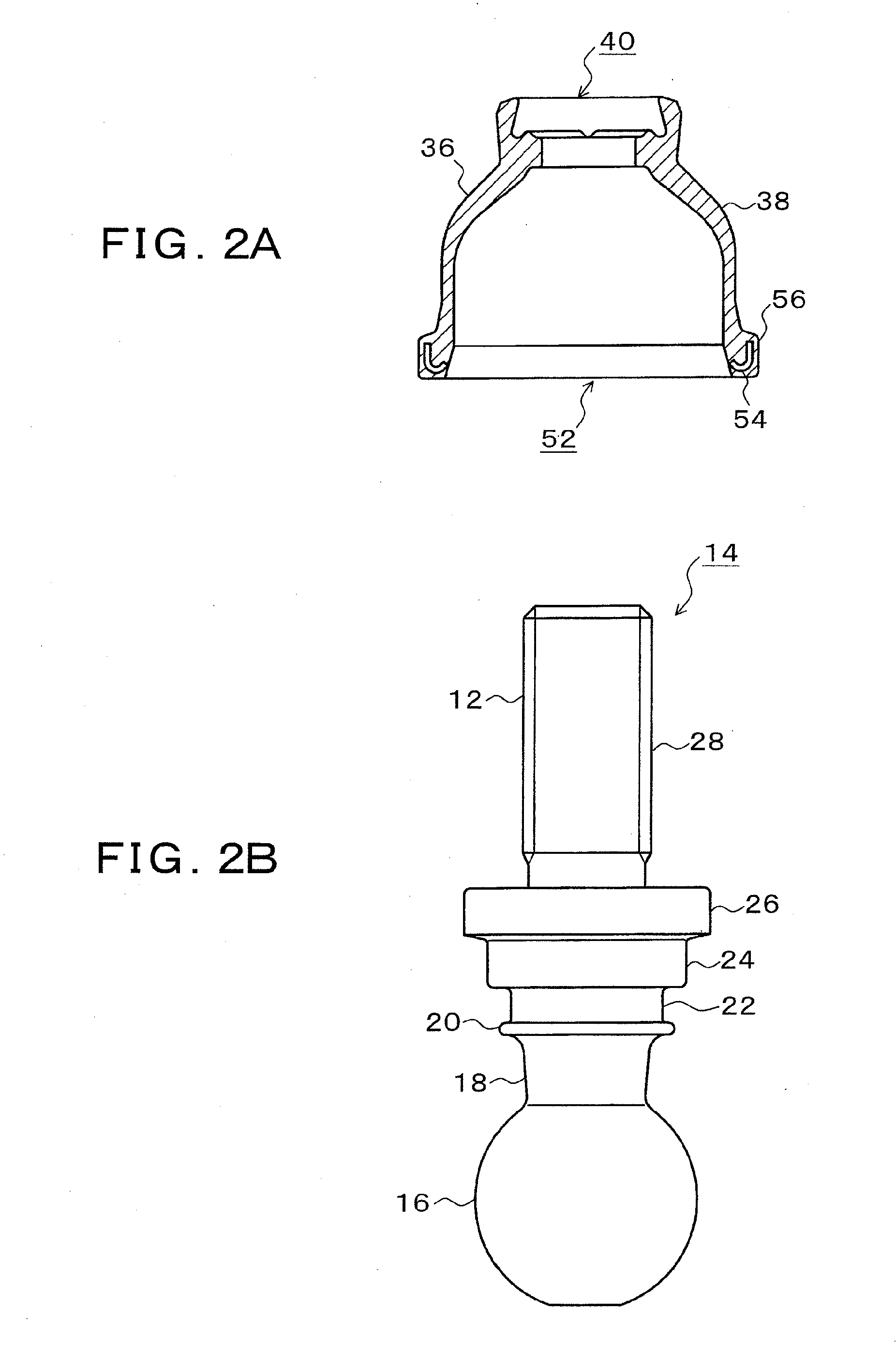
[0022]FIGS. 2A and 2B are explanatory drawings respectively showing the dust cover 36 and the ball stud 12 of FIG. 1. FIG. 2A is a cross section of the dust cover 36, and FIG. 2B shows the ball stud 12. In FIG. 2A, the dust cover 36 is formed of an elastic material such as rubber, has a small-diameter opening 40 at one end of a film part 38 and a large-diameter opening 52 at the...


PUM


Abstract

A ball joint capable of maintaining a good sealing characteristic even when a film part of a dust cover is strained and capable of improving the assembly characteristic of the dust cover is provided at low cost. In a ball joint having a ball stud having a spherical head part, a socket turnably housing the spherical head part and having an opening in one side, and a dust cover; the ball stud is provided with a first flange part, an intermediate shaft part, and a second flange part; and the dust cover is provided with an inner peripheral part sandwiched between the first flange part and the second flange part and fitting the intermediate shaft part, a lip part being in close contact with the second flange part, and a protruding part having a gap at least at one location and abutting the second flange part.

Description

TECHNICAL FIELD[0001]The present invention relates to a ball joint mainly used as a coupling device of a link mechanism for a vehicle and particularly relates to a ball joint in which the sealing characteristic of a dust cover is not reduced.BACKGROUND ART[0002]Conventionally, for example, the one described in Patent Literature 1 has been known as a ball joint which is used in a suspension mechanism or a steering mechanism of a vehicle. This ball joint has a structure in which a small-diameter side end part of a dust cover composed of an elastic material such as rubber is provided with a lip part (annular projection) which is in close contact by elasticity with the entire periphery of the outer peripheral surface of a flange part of a ball stud, and the small-diameter side end part is brought into close contact with the flange-part end surface of the ball stud by the urging force generated by the elasticity of the dust cover.[0003]Patent Literature 1: Japanese Utility Model Laid-Ope...

Claims


Application Information

Patent Timeline
IPC IPC(8): F16C11/06F16J15/52
CPCF16J3/046F16C11/0671Y10T403/32729F16C11/0628F16C11/068
Inventor SHIMAZAWA, TOSHIHIRO
Owner SHIMAZAWA TOSHIHIRO
Why Eureka
Try Eureka