Pulse wave sensor

a pulse wave and sensor technology, applied in the field of pulse wave sensors, can solve the problems of inability to successfully measure pulse wave, difficult to perform continuous pulse wave measurement for a long period, etc., and achieve the effect of reducing the effect of motion nois

Active Publication Date: 2012-06-14
ROHM CO LTD
View PDF9 Cites 58 Cited by
  • Summary
  • Abstract
  • Description
  • Claims
  • Application Information

AI Technical Summary

Benefits of technology

[0009]In consideration of the aforementioned problems discovered by the inventers of this application, a purpose of this invention is to provide a pulse wave sensor which can measure

Problems solved by technology

Therefore, though the pulse wave can be measured for short period (e.g., from few minutes to few hours), it is difficult to perform a continuous pulse wave measurement for long period (e.g., from few days to few months).
Moreover, with resp

Method used


Image

  • Pulse wave sensor
  • Pulse wave sensor
  • Pulse wave sensor

Examples


Embodiment Construction

A Principle for the Pulse Wave Measurement

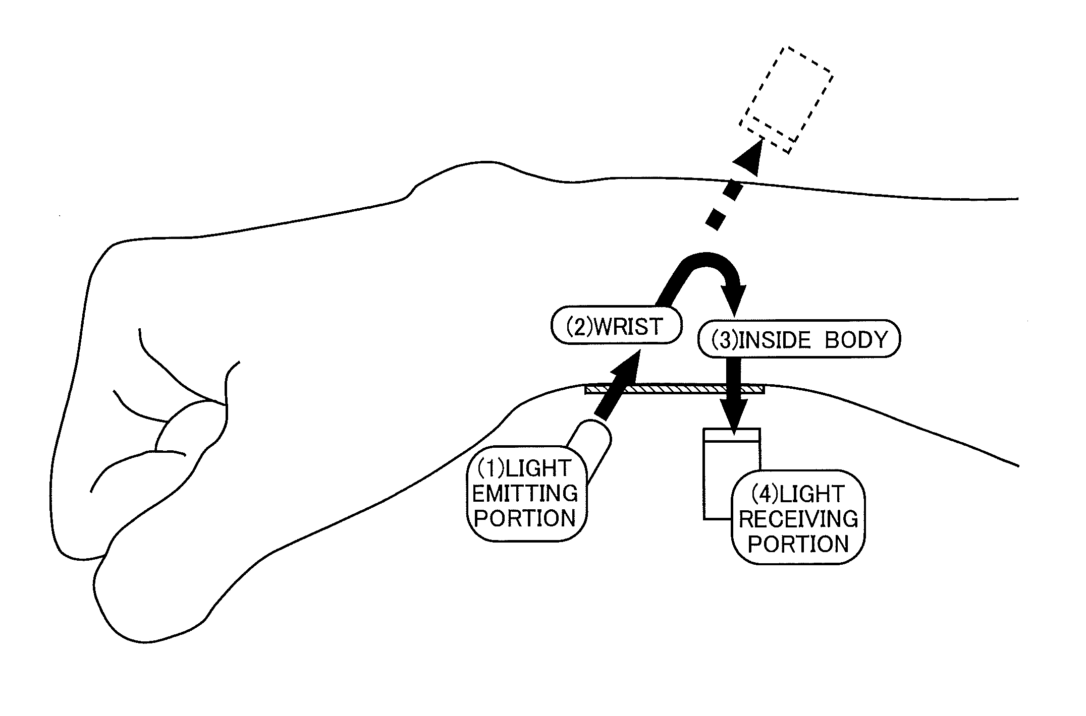
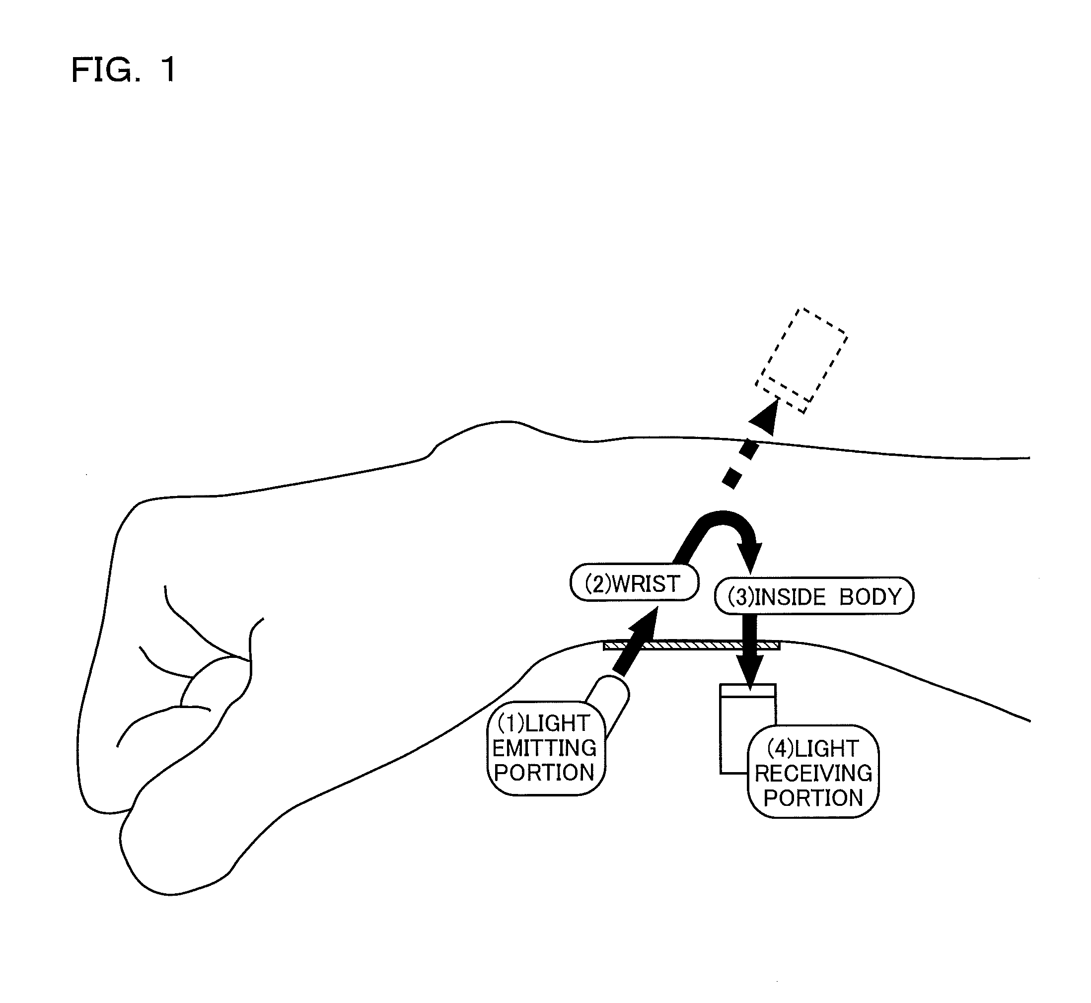
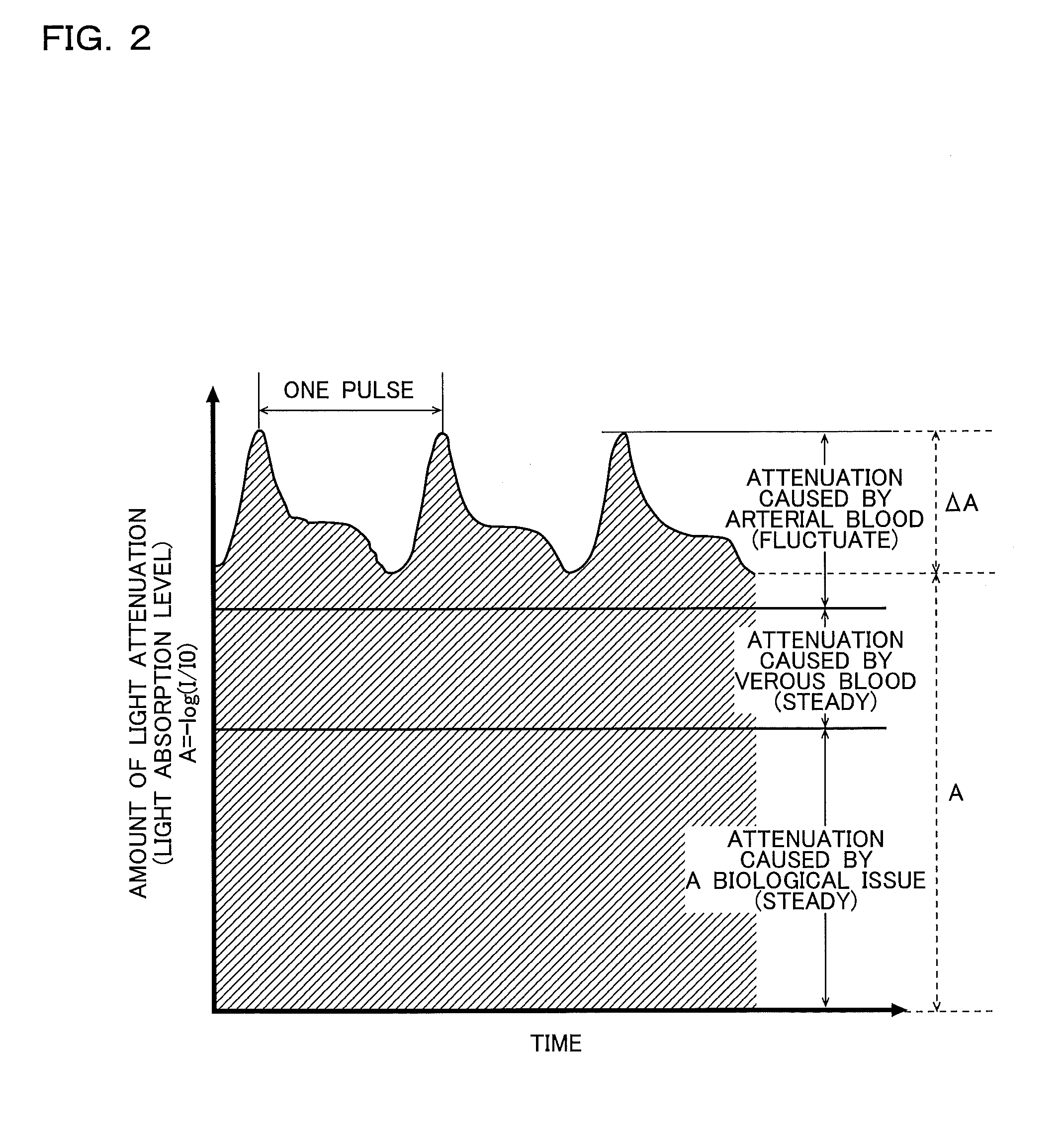
[0100]FIG. 1 is a schematic diagram to explain a principle of a pulse wave measurement in accordance with the implementation example 1 of the invention. FIG. 2 is a wave form diagram illustrating a situation where the amount of light attenuation within a living body (i.e., light absorption level) changes according to the time lapse illustrated in the pulse wave measurement in FIG. 1.

[0101]For example, with respect to a pulse measurement by means of plethysmography, as illustrated in FIG. 1, the light is emitted from the light emitting portion (e.g., LED [light Emitting Diode], etc) to part of the living body (i.e., other portions work well, the wrist shown in FIG. 1 or the fingertip illustrated in FIG. 24, for example) pressed to the measurement window. Then an intensity of the light which penetrates through the body and go out of the body is detected at the light receiving portion (e.g., a photo diode or a photo transistor). Here, as illust...


PUM


Abstract

Among the technical characteristics disclosed in this specification, the pulse wave sensor with one of the technical characteristic includes a construction to detect the pulse wave at a wrist (i.e., a construction to measure the pulse wave to be worn at the wrist). To be more concrete, the pulse wave sensor includes a measurement unit to measure the pulse wave, a power source unit to supply power to the measurement unit, a cable to connect between the measurement unit and the power source unit electrically, and a armlet type housing to contain the measurement unit, the power source unit, and the cable.

Description

CROSS-REFERENCE TO RELATED APPLICATIONS[0001]This application claims the benefit of priority of Japanese patent application No. 2010-275574 (filing date: Dec. 10, 2010) and No. 2010-275590 (filing date: Dec. 10, 2010) and No. 2011-002422 (filing date: Jan. 7, 2011), which are incorporated herein by reference in their entirety.BACKGROUND OF THE INVENTION[0002]1. Field of the Invention[0003]This invention relates to a pulse wave sensor.[0004]2. Description of Related Art[0005]Conventionally, the pulse wave sensor is a construction to measure the pulse wave by means of a light emitting portion to emit a light to a fingertip of the examinee, and a light receiving portion to detect an intensity of the light penetrates through a living body. For example, with respect to the pulse wave sensor of the conventional construction, as illustrated in FIG. 15, it has a construction to measure the pulse wave at fingertip of the examinee. Moreover, with respect to the conventional pulse wave sensor,...

Claims


Application Information

Patent Timeline
IPC IPC(8): A61B6/00A61B5/024
CPCA61B5/02007A61B5/02405A61B5/02427A61B5/14552A61B5/4815A61B5/6803A61B2562/185A61B5/6814A61B5/6826A61B2562/0219A61B2562/0233A61B2562/0238A61B2562/0247A61B5/681
Inventor TERUMOTO, KOJINIWA, DAISUKESATOMI, TSUYOSHIOGUCHI, KAZUHIRO
Owner ROHM CO LTD
Why Eureka
Try Eureka