Surgical techniques and closure devices for direct cardiac catheterization

a technology of surgical techniques and closure devices, applied in the field of minimally invasive surgical tools, can solve the problems of tearing of heart tissue in older patients, on whom cardiac procedures are most commonly performed, and achieve the effect of reducing the risk of damaging heart tissue and increasing the inwardly-directed pressur

Active Publication Date: 2012-06-14
HEALTH RAMBAM
View PDF9 Cites 12 Cited by
  • Summary
  • Abstract
  • Description
  • Claims
  • Application Information

AI Technical Summary

Benefits of technology

[0033]The loop is typically configured such that, as the loop transitions from the open shape to the closed shape, the anchors of the first, inner set move a greater distance than the anchors of the second, outer set. Movement by these two distances has the effect of applying two strengths of closure on the heart muscle: an inner, greater level of closure, surrounded by an outer, lesser level of closure. Together, the two levels of closure together tightly close the passage made through the myocardium, while minimizing the risk of damaging heart tissue.
[0034]For some applications, the anchors are configured to transition from respective initial angular orientations to respective tissue-locking angular orientations, in which each of the anchoring portions defines an angle of between 45 and 75 degrees, e.g., between 55 and 65 degrees, such as 60 degrees, with the plane defined by the opening of the loop. This angle of the anchoring portions helps lock the anchors to the cardiac tissue. In addition, when the loop assumes the closed shape, the angling of the anchoring portions increases the inwardly-directed pressure applied by the closure device to the cardiac tissue, thereby helping close the puncture through the heart wall.

Problems solved by technology

The hearts of older patients, upon whom cardiac procedures are most commonly performed, are particularly vulnerable to such tearing.

Method used


Image

  • Surgical techniques and closure devices for direct cardiac catheterization
  • Surgical techniques and closure devices for direct cardiac catheterization
  • Surgical techniques and closure devices for direct cardiac catheterization

Examples


Embodiment Construction

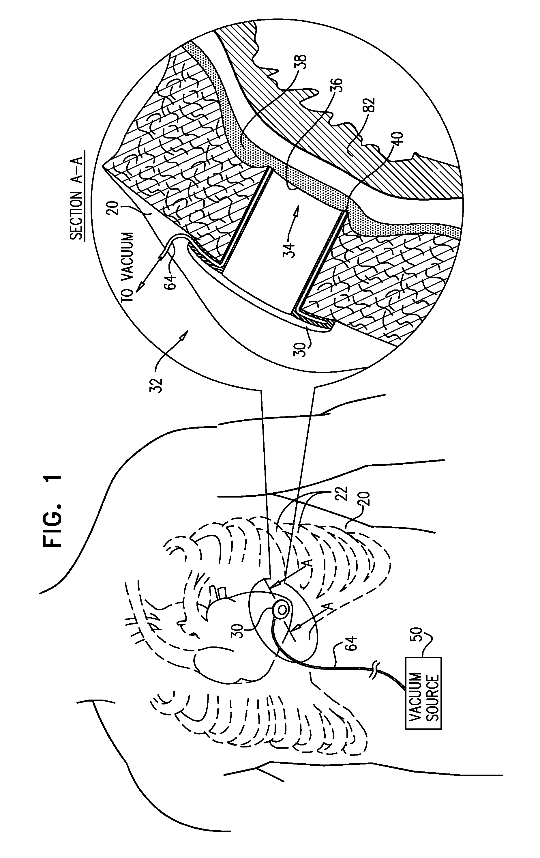
[0170]FIG. 1 is a schematic illustration of a first step of a transapical surgical procedure, in accordance with an application of the present invention. The transapical surgical procedure is typically performed to form a passage through the left or right ventricle of a beating heart, near the apex of the ventricle. A catheter is inserted through the passage into the ventricle, and is used to access the heart for performing a medical procedure, such as valve replacement (e.g., aortic or mitral valve replacement), or valve repair (e.g., atrial or mitral valve repair).

[0171]A surgeon begins the procedure by making a small incision in a chest wall 20 between two ribs 22, e.g., between the fourth and fifth ribs, or between the fifth and sixth ribs, depending on the location of the apex in the particular patient, typically after administering local anesthesia. The surgeon passes an outer tubular tool 30 of a transapical surgical system 32 through chest wall 20. Typically, the ribs do not...


PUM


Abstract

A surgical closure device (100) includes (a) a continuous loop (110), which defines an opening (112) therethrough, and which is configured to assume at least an open shape and a closed shape, and (b) four or more tissue anchors (130), coupled to the loop (110). An area of the opening (112) when the loop (110) assumes the closed shape is less than 80% of the area of the opening (112) when the loop (110) assumes the open shape. The loop (110) is configured such that, as the loop (110) transitions from the open shape to the closed shape, all of the anchors (130) move in generally radial directions, and do not move in generally circumferential directions; and a first set of two or more of the anchors (130A) move on average a first distance, and a second set of two or more of the anchors (130B) move on average a second distance that is between 40% and 80% of the first distance.

Description

CROSS-REFERENCE TO RELATED APPLICATIONS[0001]The present application claims priority from U.S. Provisional Application 61 / 234,691, filed Aug. 18, 2009, entitled, “Surgical techniques and closure devices for direct cardiac catheterization,” which is assigned to the assignee of the present application and is incorporated herein by reference.FIELD OF THE APPLICATION[0002]The present invention relates generally to cardiac surgical methods and devices, and specifically to minimally-invasive surgical tools and methods for performing transapical surgical procedures.BACKGROUND OF THE APPLICATION[0003]Various cardiac medical procedures are performed using transapical delivery of medical devices to the left or right ventricle. The ventricle is accessed directly through a passage formed through the myocardium near the apex of ventricle. Such medical procedures include valve replacement, such as aortic or mitral valve replacement, and valve repair, such as mitral valve repair. Conventional tran...

Claims


Application Information

Patent Timeline
Patent Type & Authority Applications(United States)
IPC IPC(8): A61B17/04
CPCA61B17/0057A61B17/3415A61B17/3421A61B2017/00243A61B2017/00637A61B2017/3425A61B2017/00867A61B2017/0641A61B2017/0645A61B2017/306A61B2017/00668
Inventor BOLOTIN, GIL
Owner HEALTH RAMBAM
Why Eureka
Try Eureka