
Hydroprocessing Catalysts and Methods for Making Thereof

Active Publication Date: 2012-06-21
CHEVROU USA INC
View PDF5 Cites 7 Cited by
  • Summary
  • Abstract
  • Description
  • Claims
  • Application Information

AI Technical Summary

Benefits of technology

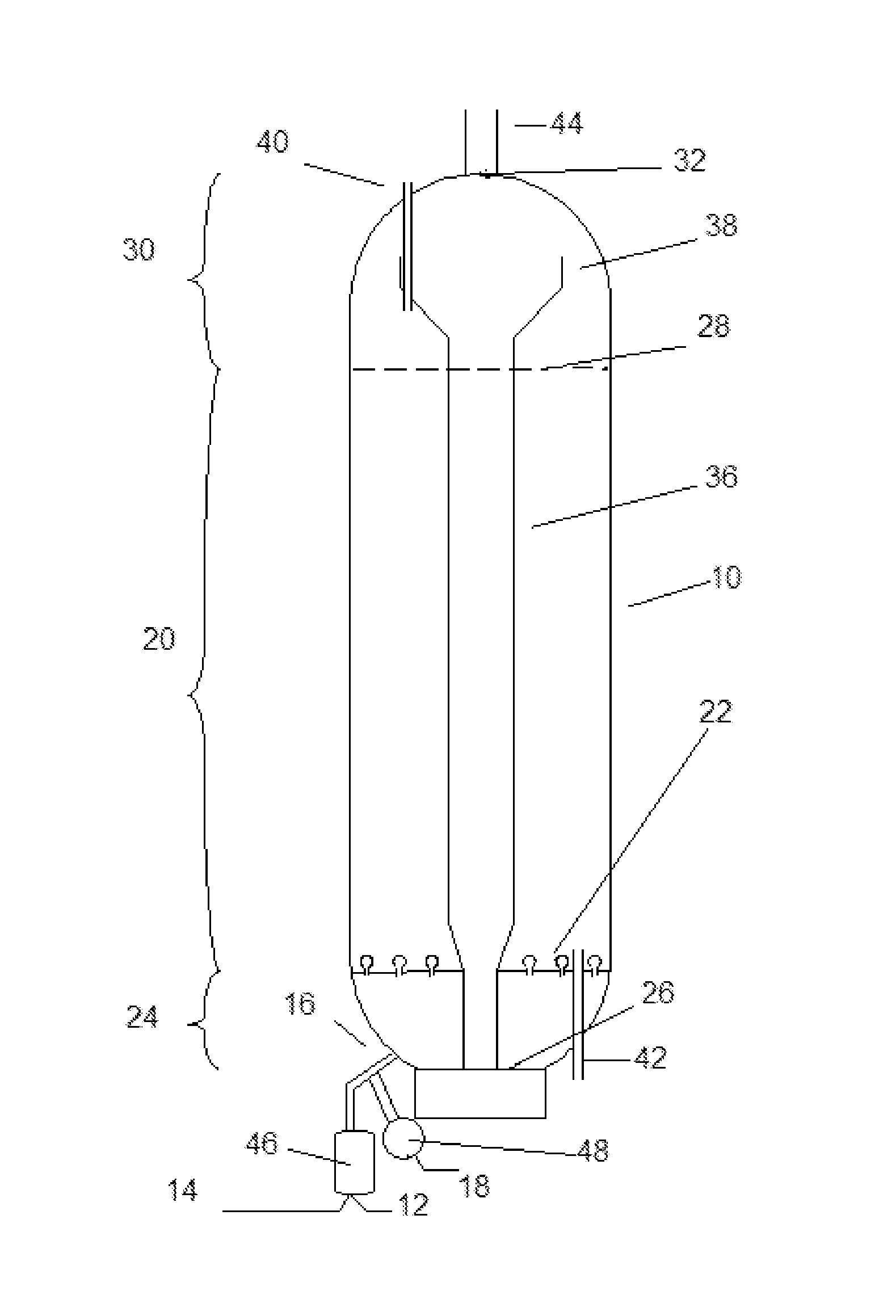
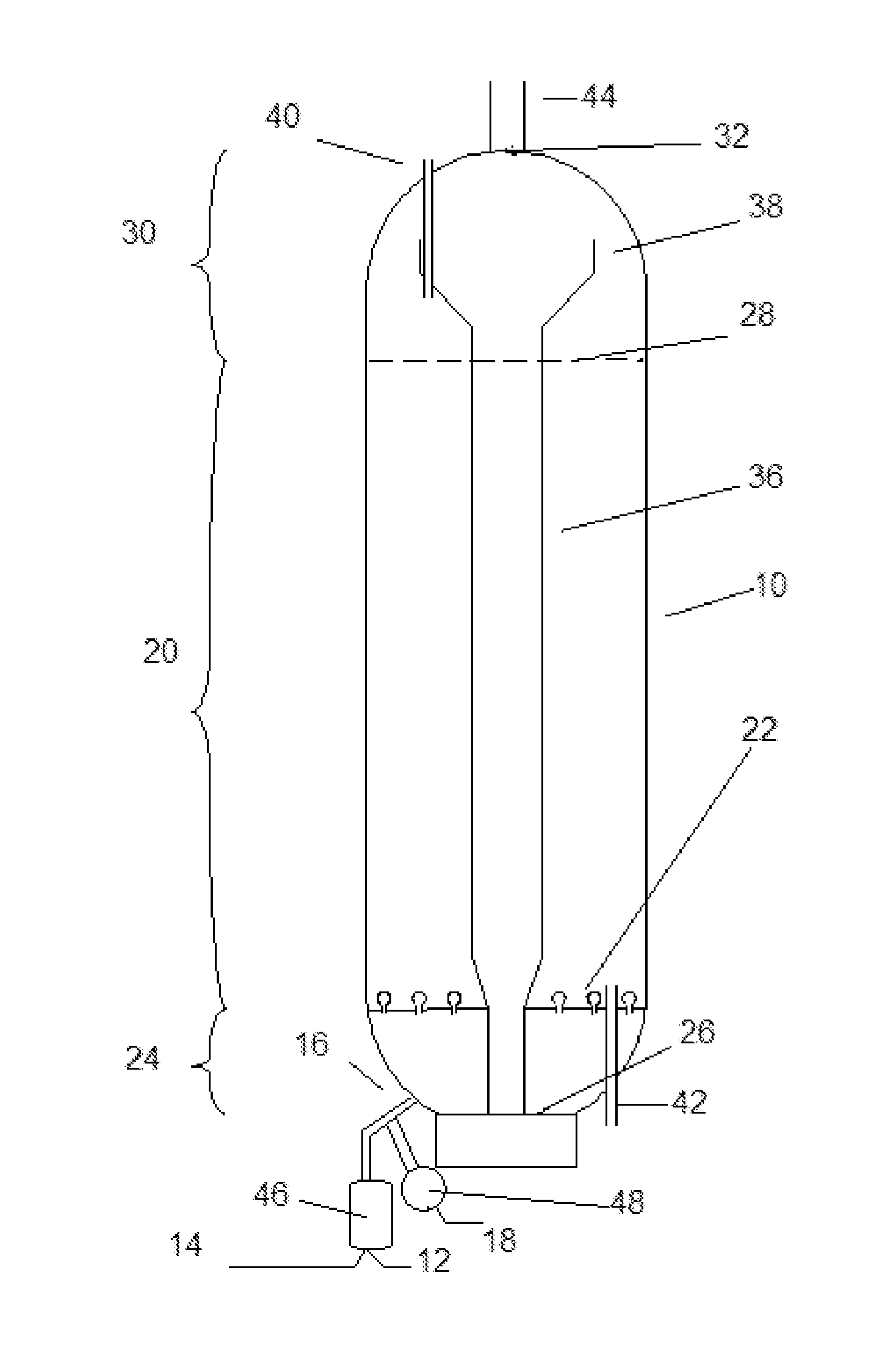
[0011]In yet another aspect, the invention relates to a method of upgrading a pre-existing ebullated bed hydroprocessing system in order to reduce formation of coke and / or sediment, comprising: (a) operating a pre-existing ebullated bed hydroprocessing system comprising one or more ebullated bed reactors, each of which comprises a liquid hydrocarbon phase, a solid phase comprised of an expanded bed of particulate catalyst, a gaseous phase comprising hydrogen gas, and catalyst free zones above and below the expanded bed of the particulate catalyst; (b) providing a sulfided slurry catalyst having an average particle size ranging from 1 to 300 μm; (c) introducing a heavy oil feedstock and the slurry catalyst into at least one ebullated bed reactor, wherein the slurry catalyst is dispersed throughout the liquid hydrocarbon phase of the pre-existing ebullated bed hydroprocessing system; and (d) operating the upgraded ebullated bed hydroprocessing system to form a hydroprocessed material, wherein the introduction of the slurry catalyst reduces formation of coke or sediment in the upgraded ebullated bed hydroprocessing system compared to the pre-existing ebullated bed hydroprocessing system.
[0012]In another aspect, the invention relates to a method of hydroprocessing a heavy oil feedstock. The method comprises: (a) introducing to an ebullated reactor a heavy oil feedstock feed and a slurry catalyst having an average particle size ranging from 1 to 300 μm; heating or maintaining the heavy oil feedstock at a hydrocracking temperature to yield an upgraded material; wherein the ebullated bed reactor comprising: a liquid phase comprised of hydrocarbons and the slurry catalyst; a solid phase comprised of a particulate catalyst within an expanded catalyst bed; a gaseous phase comprised of hydrogen; and zones above and below the expanded catalyst bed that are devoid of the particulate catalyst, and wherein the slurry catalyst being dispersed throughout the liquid phase, including the particulate catalyst free zones, and catalyzing reactions between the hydrogen and free radicals formed from the heavy oil feedstock throughout the liquid phase, including the particulate catalyst free zones, to yield an upgraded material while reducing or eliminating formation of coke precursors and sediment within the ebullated bed reactor compared to an ebullated bed reactor in the absence of the slurry catalyst.

Problems solved by technology

Heavy oil is particularly difficult to upgrade in refinery operations.
Heavy oils often contain high concentrations of sulfur and nitrogen, which are difficult to remove to the extent necessary for further processing of the upgraded products from heavy oil processing.
The aromatic character of many heavy oils tends to contribute to instability of the upgraded products.
While heating the heavy oils, even in the presence of high pressure hydrogen, components of the heavy oil thermally crack to yield free radicals, which quickly combine to make sediment and coke precursors unless they are quickly suppressed by active catalysis.
Furthermore, during catalysis, high molecular weight coke precursors deposit on catalysts and quickly reduce catalytic activity.
Rapid deactivation of catalysts used in heavy oil processing service often requires frequent replacement of catalysts in the heavy oil processing systems.
The single-metallic colloidal catalyst employed is synthesized in-situ upon mixing with the heavy oil feedstock under sufficient conditions for sulfidation to occur; thus tight control of the catalyst properties is difficult.

Method used


Image

  • Hydroprocessing Catalysts and Methods for Making Thereof
  • Hydroprocessing Catalysts and Methods for Making Thereof

Examples


example 1

[0103]A commercially available particulate catalyst from Advanced Refining Technology (ART) was provided as a particulate catalyst. The particulate catalyst had a nominal cross-sectional diameter of 0.04 inch and a length of 0.1 inch to 0.4 inch, and contained 10% by weight molybdenum and 5% by weight nickel on an alumina base. Properties of the particulate catalyst are listed in Table 1.

TABLE 1Particulate CatalystRework MaterialMolybdenum content, wt. %  10 wt. %  10 wt. %Nickel content, wt. %   5 wt. %   5 wt. %Surface Area, m2 / g  288 m2 / g  288 m2 / gPore Volume0.724 cm3 / g0.724 cm3 / g(by mercury porosimetry)Mesopore Volume (by mercury0.162 cm3 / g0.162 cm3 / gporosimetry in 100-300 A range)

example 2

[0104]The particulate catalyst was dried for 1 hour under nitrogen at 400° F. A 1% dimethyldisulfide (DMDS) solution in heptane was injected for 1 h at 350° F. and at a pressure of 300 psi before ramping the temperature to 450° F. Sulfiding was maintained for 14 hours at these conditions before introducing a 6% DMDS solution and increasing pressure to 800 psi followed by ramping to 650° F., where the temperature was maintained for 2 hours.

example 3

[0105]A sample of the particulate catalyst of Example 1 was ground, and the fraction that passed through a standard 650 mesh screen was collected as rework material. Properties of the rework material are listed in Table 1.

[0106]An unsulfided catalyst slurry containing 92 grams of the rework material and 7562 grams of the diluent blend having properties listed in Table 2 was prepared.


PUM

PropertyMeasurementUnit
Fractionaaaaaaaaaa
Fractionaaaaaaaaaa
Pore sizeaaaaaaaaaa

Abstract

A method to upgrade heavy oil feedstock using an ebullated bed reactor and a novel catalyst system is provided. The ebullated bed reactor system includes two different catalyst with different characteristics: an expanded catalyst zone containing particulate catalyst having a particle size of greater than 0.65 mm; and a slurry catalyst having an average particle size ranging from 1 to 300 μm. The slurry catalyst is introduced to the ebullated bed system with the heavy oil feedstock, and entrained in the upflowing hydrocarbon liquid passing through the ebullated bed reaction zone. The slurry catalyst reduces the formation of sediment and coke precursors in the ebullating bed reactor system. The slurry catalyst is prepared from at least a water-soluble metal precursor and pre-sulfided prior to being introduced with the heavy oil feedstock to the reactor system, or sulfided in-situ in the ebullated bed reactor in another embodiment.

Description

RELATED APPLICATIONS[0001]This application claims benefit under 35 USC 119 of U.S. Provisional Patent Application Nos. 61 / 424,804 with a filing date of Dec. 20, 2010; 61 / 428,599 with a filing date of Dec. 30, 2010; and 61 / 562,850 with a filing date of Nov. 22, 2011. This application claims priority to and benefits from the foregoing, the disclosures of which are incorporated herein by reference.TECHNICAL FIELD[0002]The invention relates generally to catalysts for use in the conversion of heavy oils and residua and methods for making thereof.BACKGROUND OF THE INVENTION[0003]Heavy oil is particularly difficult to upgrade in refinery operations. Metals contained in the oil tend to rapidly deactivate catalysts with which they come in contact during the upgrading process. Heavy oils often contain high concentrations of sulfur and nitrogen, which are difficult to remove to the extent necessary for further processing of the upgraded products from heavy oil processing. The aromatic characte...

Claims


Application Information

Patent Timeline
IPC IPC(8): C10G47/06C10G45/00C10G35/085B01J31/28B01J27/043B01J27/24B01J27/053B01J31/34C10G35/06B01J27/047
CPCC10G49/02C10G2300/4056C10G2300/70C10G2300/708C10G2300/802B01J37/20B01J35/0006B01J23/883B01J35/023B01J35/1019B01J35/1023B01J35/1042B01J35/1047B01J35/1052B01J35/1066B01J35/1076B01J37/0036B01J37/0201C10G2300/208C10G49/12B01J35/19B01J35/40B01J35/617B01J35/638B01J35/64B01J35/615B01J35/651B01J35/657B01J35/635B01J23/28B01J37/02B01J35/51
Inventor REYNOLDS, BRUCE E.CHABOT, JULIEMARIS, ERINSOLBERG, SEANCHEN, KAIDONG
Owner CHEVROU USA INC
Learn More