
Electrical heating device

Inactive Publication Date: 2012-06-21
EBERSPACHER CATEM
View PDF2 Cites 7 Cited by
  • Summary
  • Abstract
  • Description
  • Claims
  • Application Information

AI Technical Summary

Benefits of technology

[0006]The object of the present invention is to provide an electrical heating device of the type mentioned in the introduction, which can be operated safely even at high operating voltages.
[0008]With the present invention safe contact protection is provided so that it is no longer necessary to provide an insulating layer between the heat generating elements and the heat emitting elements. The efficiency of the heating device according to the invention is therefore improved compared to the prior art of EP 1 768 459 A1, particularly if a multi-layered redundant insulating layer is formed which has relatively poor thermal conductivity.
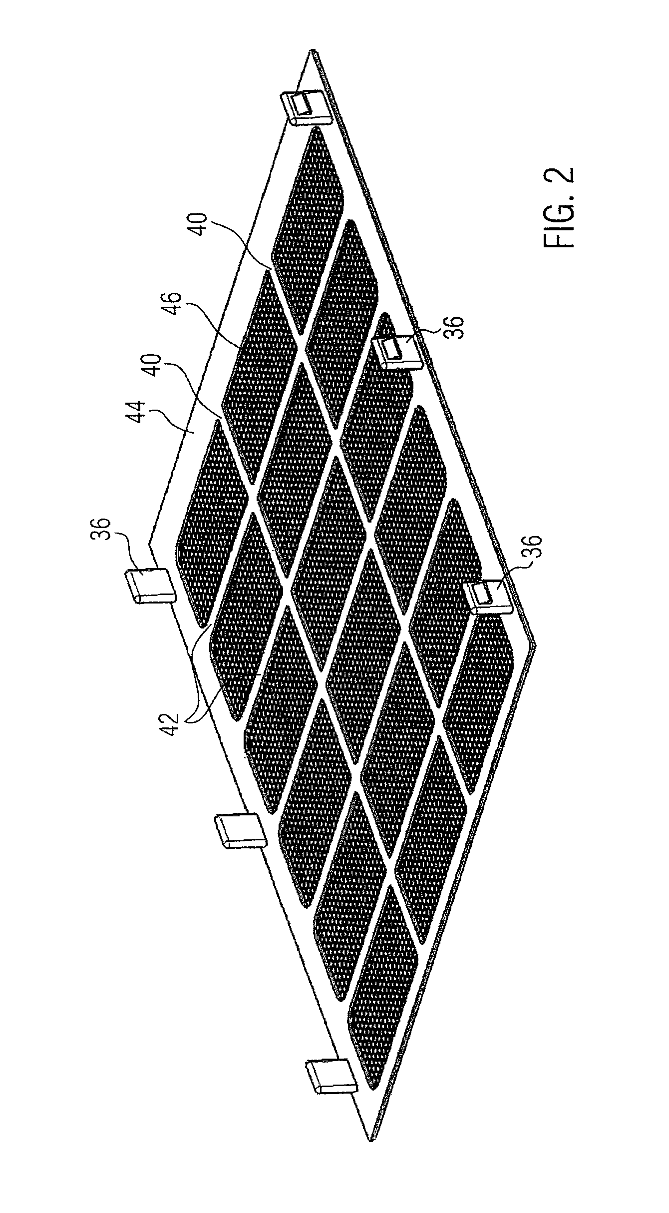
[0011]According to a further development of the present invention in which the plastic mesh is mounted on a strut arrangement, the struts of which span the respective housing openings, the plastic mesh is prevented from abutting the surface of the heating block. The strut arrangement can be formed from one or more mutually parallel struts or also a grid arrangement. The individual struts or grid bars of the strut arrangement are preferably formed so rigidly that with normal loads no significant deflection occurs such that the plastic mesh can abut the surface of the heating block exposed towards the housing opening.
[0012]With regard to an economical manufacture, according to a further development of the present invention it is suggested that the plastic mesh is joined to the struts of the strut arrangement by overmoulding of the plastic mesh with a plastic component forming the strut arrangement. Consequently, during the manufacture of the electrical heating device the plastic mesh is placed into an injection mould, which comprises a mould cavity for moulding the strut arrangement. The mould cavity is here preferably formed such that the plastic component for forming the strut arrangement is not only formed on one side of the plastic mesh, but also on the opposite side so that after overmoulding on both sides of the plastic mesh, the plastic mesh is sealed in as a rigid plastic component. The strut or grid arrangement is here preferably formed such that the struts which in each case extend parallel to the heating block layers are located at the same height as the heat generating elements so that the medium to be heated can flow over the heat emitting elements without hindrance.

Problems solved by technology

This electrical insulation however also causes a certain thermal insulation by means of which the efficiency of the PTC elements is impaired.

Method used


Image

  • Electrical heating device
  • Electrical heating device
  • Electrical heating device

Examples


Embodiment Construction

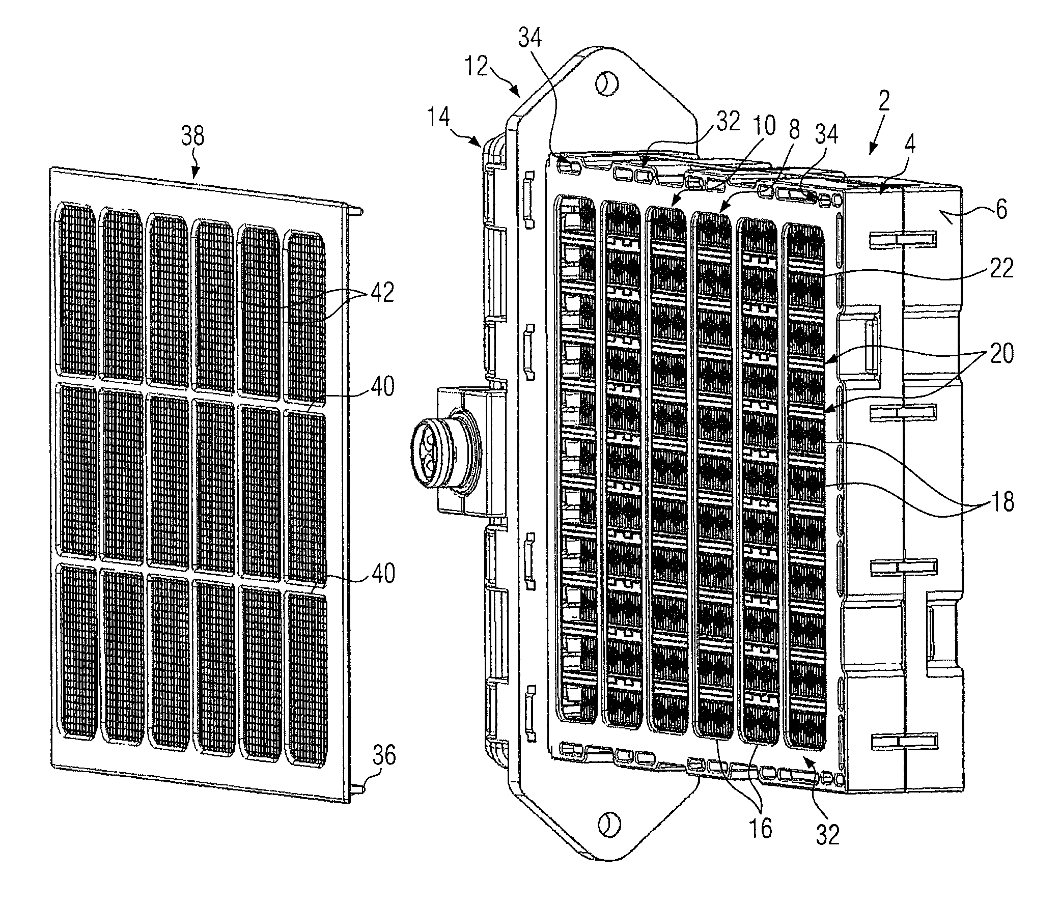
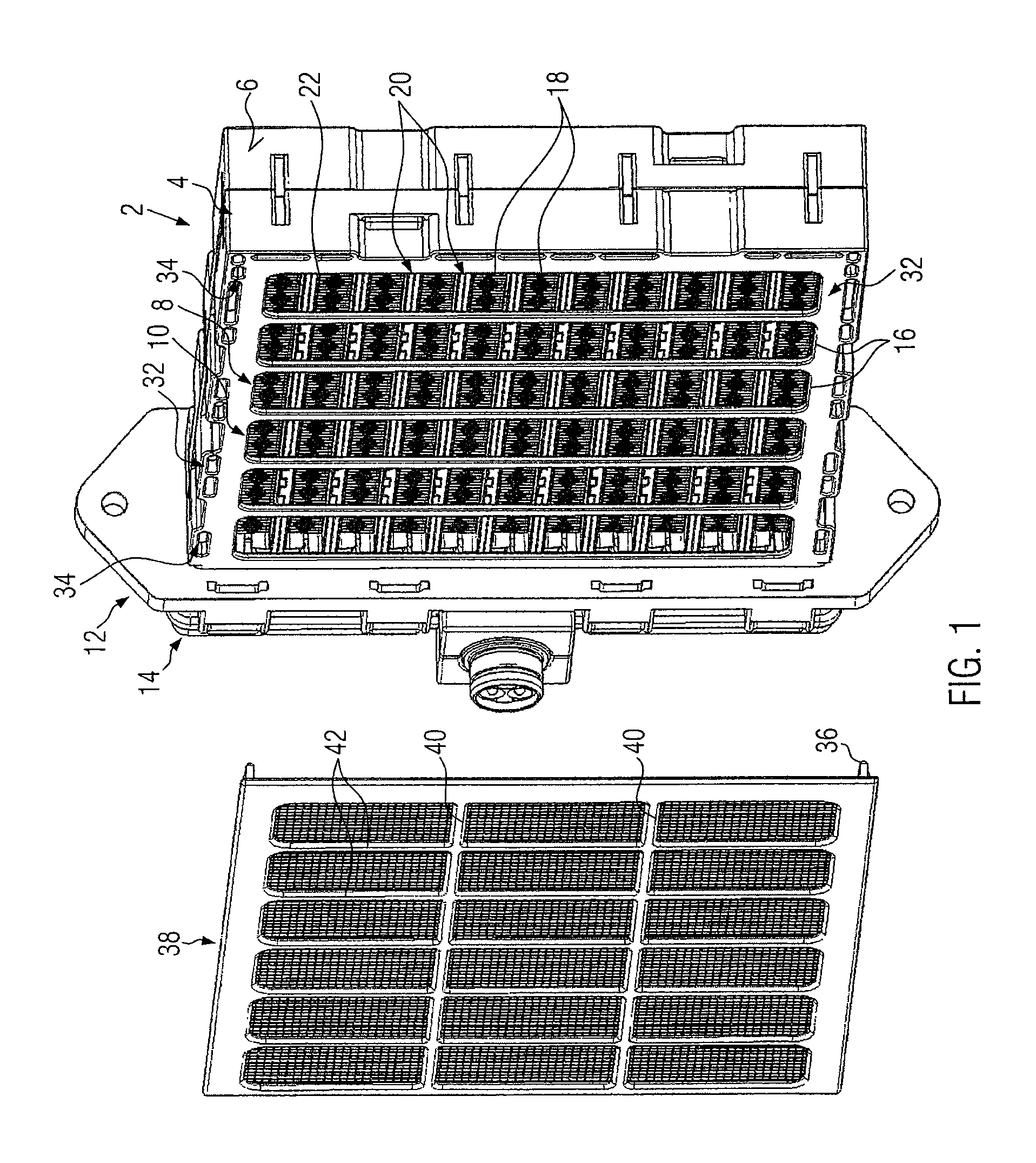
[0027]FIG. 1 illustrates an electrical heating device as auxiliary heating for a motor vehicle with a housing 2 comprising two identically formed housing parts 4, 6, which are joined by clipping, thus enclosing a heating block 8. The housing parts 4, 6 each have a housing opening 10 which is open to the heating block 8 and are joined on their connecting side to a flange 12 which provides access to and holds the electrical plug contacts for the connection of the heating block 8 as well as a controller enclosed by a control housing 14.

[0028]FIG. 1 shows the embodiment from the flow inlet side. Here, the housing opening 10 of the housing part 4 is penetrated by five cross struts 16. The longitudinal spars 16 extend at right angles to the parallel layers of the heating block 8. These layers are formed by heat emitting elements in the form of radiator elements 18 and heat generating elements 20 accommodated between them.

[0029]As emerges particularly from FIG. 5, the heat generating eleme...


PUM


Abstract

An auxiliary electrical heating device for a motor vehicle includes a heating block that includes parallel layers of at least one heat emitting element and at least one heat generating element. The heating block is held in a housing having oppositely situated housing openings. In order to permit the electrical heating device to be operated safely even at high operating voltages, a contact protection of an insulating material covers the respective housing openings.

Description

BACKGROUND OF THE INVENTION[0001]1. Field of the Invention[0002]The present invention relates to an electrical heating device, in particular to a heating device as auxiliary heating for a motor vehicle, with a heating block that has parallel layers of at least one heat emitting and one heat generating element, which layers are enclosed by a housing that has oppositely situated housing openings formed therein.[0003]2. Description of the Related Art[0004]An electrical heating device of this nature is known for example from EP 1 768 459 A1 which originates from the applicant. A generic electrical heating device of the above-mentioned type normally has a heat generating element with at least one PTC element, on the oppositely situated lateral faces of which electrically conducting sheet metal bands abut, through which the PTC element is supplied with electrical current. This electrical supply is normally provided at 12 volts. This operating voltage is harmless, so that normally no speci...

Claims


Application Information

Patent Timeline
IPC IPC(8): H05B3/06
CPCF24H3/0405F24H9/2071F24H9/1872F24H3/0429F24H3/0464B60H1/22H05B3/14
Inventor BOHLENDER, FRANZBEETZ, KLAUS
Owner EBERSPACHER CATEM
Learn More