System and method for producing and using multiple electron beams with quantized orbital angular momentum in an electron microscope

a technology of orbital angular momentum and electron microscope, which is applied in the direction of material analysis using wave/particle radiation, instruments, nuclear engineering, etc., can solve the problems of difficult to produce quantized phase dislocations (vortices) with integer helicity, the placement of electron optical elements after specimens, and the widespread use of phase plate-enhanced electron microscopy

Inactive Publication Date: 2012-06-21
MCMORRAN BENJAMIN
View PDF3 Cites 26 Cited by
  • Summary
  • Abstract
  • Description
  • Claims
  • Application Information

AI Technical Summary

Problems solved by technology

This represents a drawback that the electron optical elements are placed after a specimen in a TEM, as opposed to before the specimen.
Moreover, the structure's shape and material may be required to be kept completely clean from surface contamination since local charging may change the electron optical path length.
These drawbacks may have so far prevented the widespread use of phase plate-enhanced electron microscopy.
A drawback of this technique is that it may only work for particular electron beam energies, and it may be difficult to produce quantized phase dislocations (vortices) with integer helicity.
Another drawback of this technique is that it may not be feasible to cre

Method used


Image

  • System and method for producing and using multiple electron beams with quantized orbital angular momentum in an electron microscope
  • System and method for producing and using multiple electron beams with quantized orbital angular momentum in an electron microscope
  • System and method for producing and using multiple electron beams with quantized orbital angular momentum in an electron microscope

Examples


Embodiment Construction

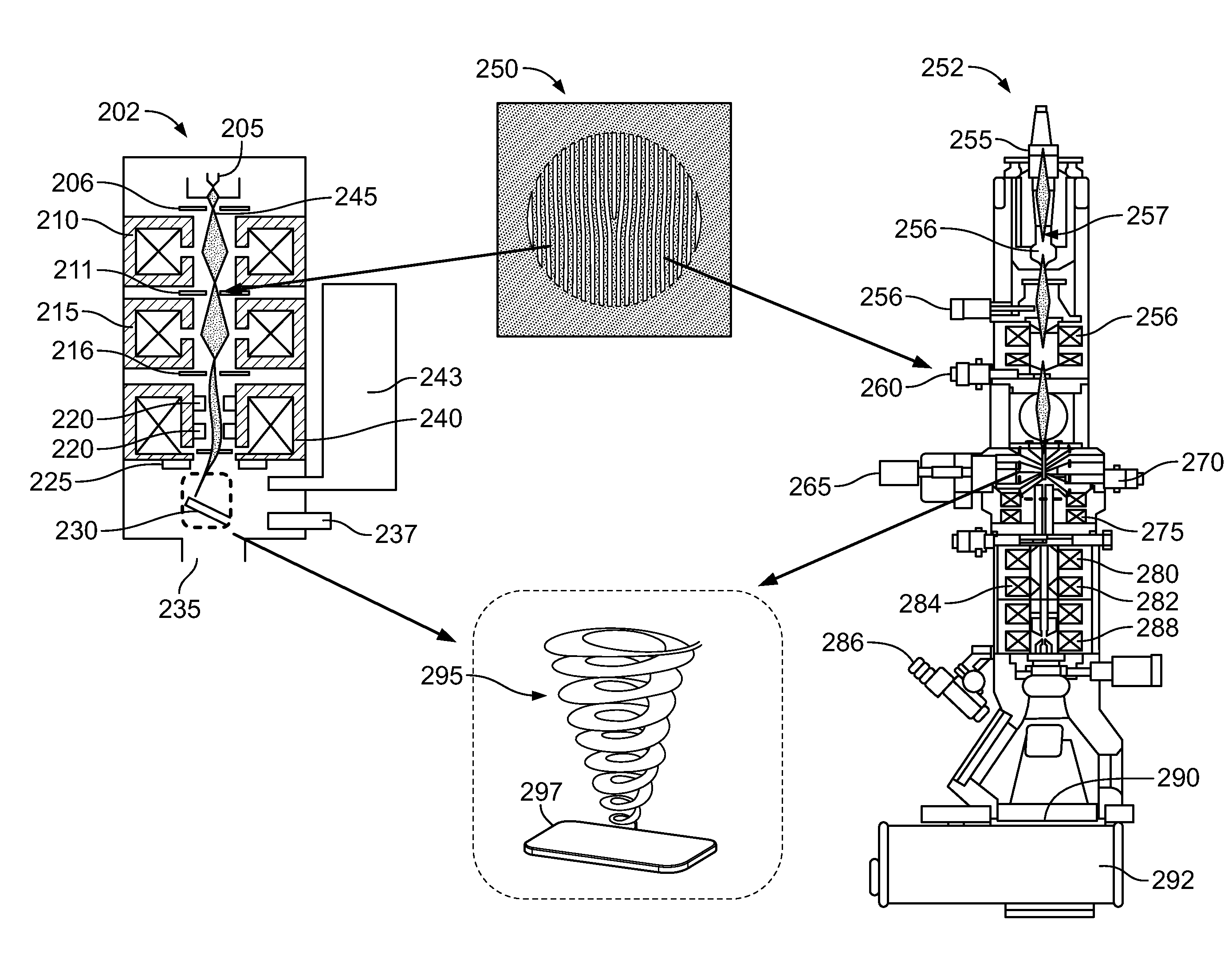
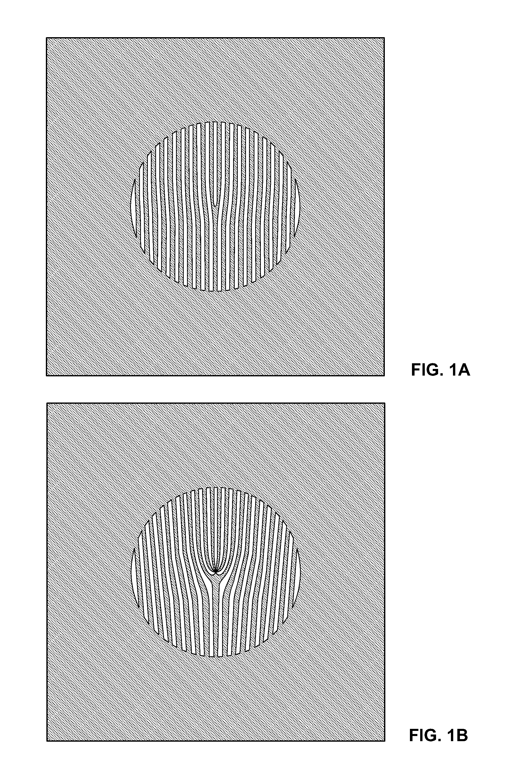
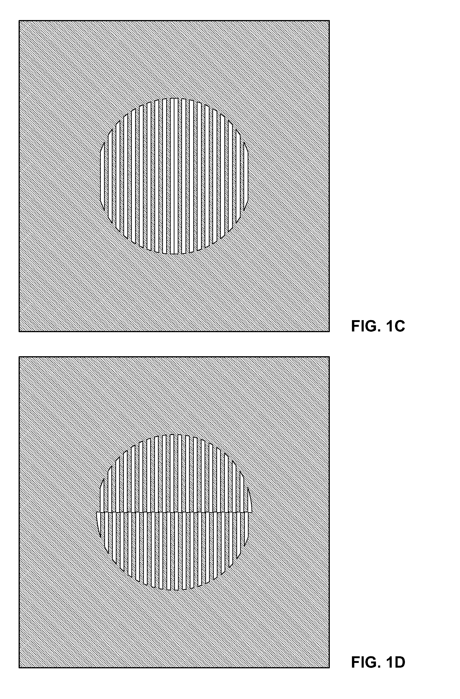
[0030]A system and method are described for producing electron probe beams with engineered phase dislocations in electron-producing imaging instruments, including electron microscopes. These beams may be used to provide information about a specimen that may not otherwise be available. Different phase dislocations may result in various unique beam interactions with a specimen.

[0031]The system and method of the present disclosure differ from the prior art in that they incorporate a scanned electron probe arrangement. Accordingly, phase dislocations may be imprinted onto the electron beam before the specimen, as opposed to after the specimen like the prior art. The present system and method also incorporate use of a diffraction hologram, as opposed to a refractive hologram. The techniques described herein provide for practical and useful electron optical elements that are capable of being reliably, reproducibly and economically manufactured. These techniques are also robust and long-la...


PUM


Abstract

A system and method for using electron beams with engineered phase dislocations as scanned probes in electron probe beam instruments such as scanning transmission electron microscopes. These types of electron beams have unique properties and can provide better information about a specimen than conventional electron beams. Phase dislocations may be created based on a pattern disposed on a nanoscale hologram, which may be placed in the electron optical column of the electron probe beam instrument. When an electron beam from the instrument is directed onto the hologram, phase dislocations may be imprinted onto the electron beam when electrons are diffracted from these holograms. For example, electron probe beams with spiral phase dislocations may occur. These spiral phase dislocations are formed using a hologram with a fork-patterned grating. Spiral phase dislocations may be used to provide magnetic contrast images of a specimen.

Description

STATEMENT REGARDING FEDERALLY SPONSORED RESEARCH / DEVELOPMENT[0001]The subject matter of this patent application was invented under the support of at least one United States Government contract. Accordingly, the United States Government may manufacture and use the invention for governmental purposes without the payment of any royalties.CROSS-REFERENCE TO RELATED APPLICATIONS[0002]N / A.BACKGROUND OF THE INVENTION[0003]1. Field of Invention[0004]The present disclosure relates to electron beam production and, more particularly, to the production of electron beams with various types of phase dislocations in scanning imaging instruments.[0005]2. Description of Related Art[0006]Electron beams may be produced having different phase dislocations in an electron microscope. Phase-dislocated beams may be used to provide additional information about a specimen when used for illumination or as a probe in an electron microscope. This additional information may be due to the different interaction be...

Claims


Application Information

Patent Timeline
IPC IPC(8): H01J37/26
CPCH01J37/28H01J2237/06383H01J2237/2802H01J2237/2614H01J2237/24557
Inventor MCMORRAN, BENJAMIN
Owner MCMORRAN BENJAMIN
Why Eureka
Try Eureka