
LED package

a technology of led packaging and led diodes, applied in the direction of display means, semiconductor devices, electrical apparatus, etc., can solve the problem that the packaging structure according to the related art may have quality defects, and achieve the effect of improving reliability

Active Publication Date: 2012-06-21
SAMSUNG ELECTRONICS CO LTD
View PDF5 Cites 12 Cited by
  • Summary
  • Abstract
  • Description
  • Claims
  • Application Information

AI Technical Summary

Benefits of technology

The present invention provides an LED package with improved reliability by preventing the filling member from easily separating from the package body. The LED package also minimizes thermal deformation of the package body and filling member to prevent damage to the LED. The LED package includes an LED, lead frames, a package body, and a filling member. The package body has a receiving groove with supporting units that engage with the filling member. The filling member has an engaging groove that matches the supporting unit. The supporting unit has an inclination surface and side surfaces that have an asymmetrical structure. The LED package also includes a lens unit on the filling member.

Problems solved by technology

This package structure according to the related art may has quality defects, such as the detachment of the LED due to the thermal deformation of the package body, and a delamination phenomenon caused in an interface between a filling member in the cavity and the package body, when the package structure is used in the rigorous condition of high temperature.

Method used


Image

  • LED package
  • LED package
  • LED package

Examples


Embodiment Construction

[0033]A light emitting diode (LED) according to an exemplary embodiment of the present invention will now be described in detail with reference to the accompanying drawings. The invention may, however, be embodied in many different forms and should not be construed as being limited to the embodiment set forth herein. Rather, this embodiment is provided so that this disclosure will be thorough and complete, and will fully convey the scope of the invention to those skilled in the art.

[0034]In the drawings, the shape and the size of components shown in drawings are exaggerated for clarity. The same or equivalent elements are referred to by the same reference numerals throughout the specification.

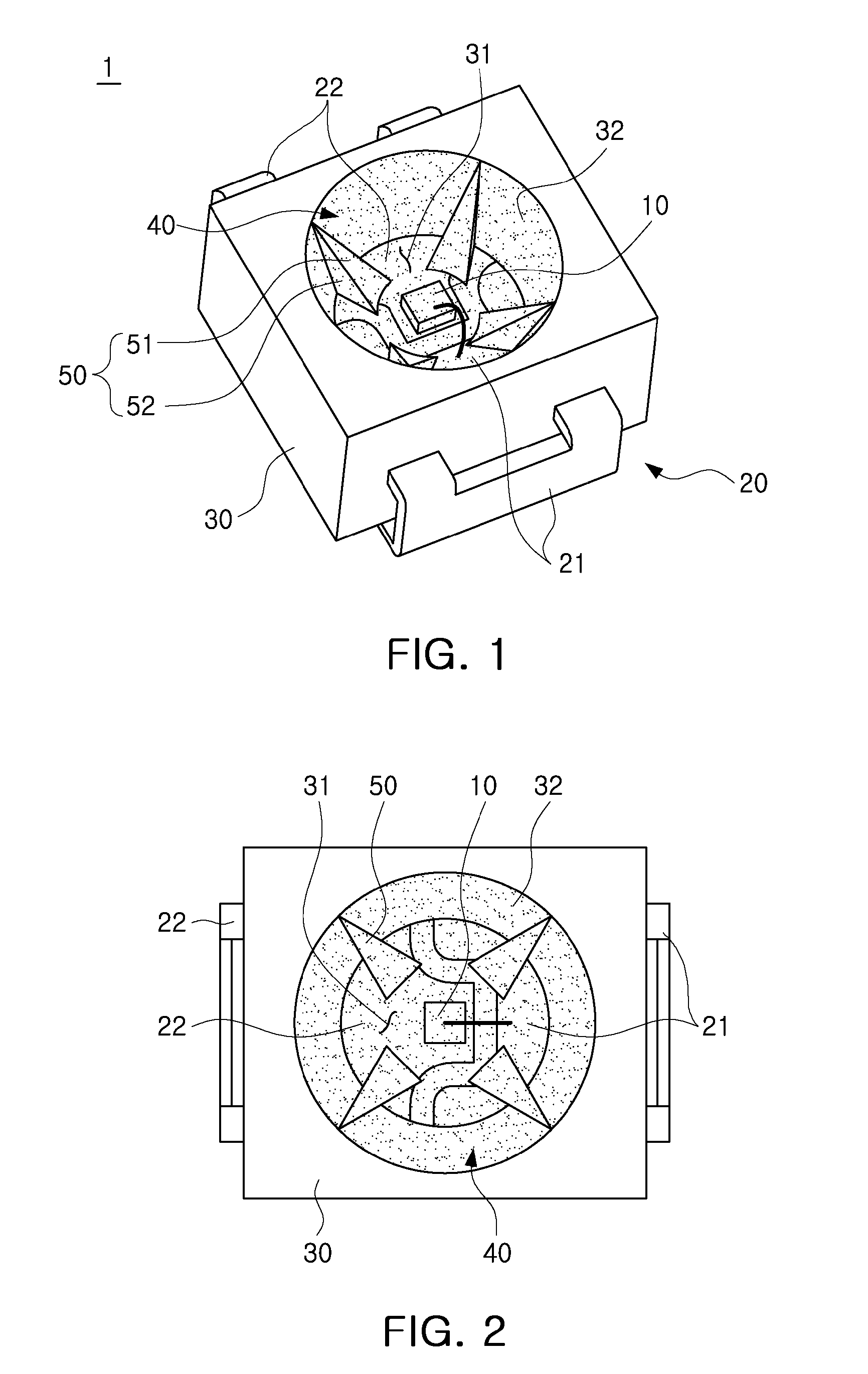
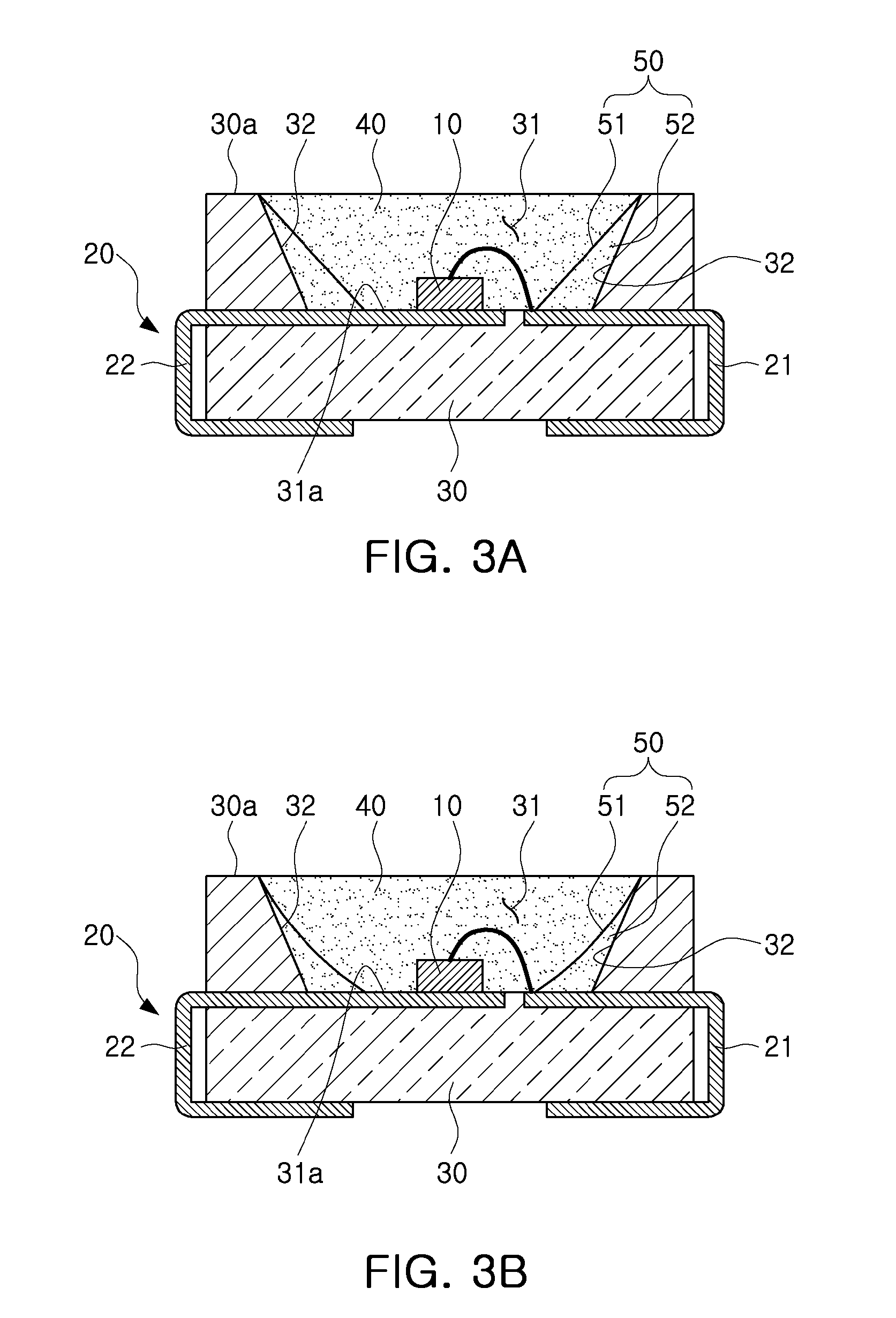
[0035]An LED package according to an exemplary embodiment of the present invention will be explained with reference to FIGS. 1 through 3.

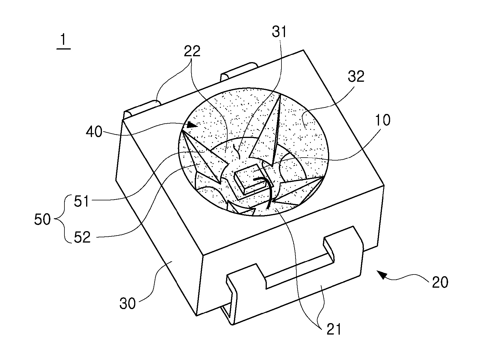
[0036]FIG. 1 is a schematic perspective view of an LED package according to an exemplary embodiment of the present invention. FIG. 2 is a schematic plan view ...


PUM


Abstract

A light emitting diode (LED) package is provided. The LED package includes an LED, a plurality of lead frames electrically connected with the LED, a package body having a receiving groove exposed to receive the LED therein and including a plurality of supporting units provided to project from an inner side surface of the receiving groove, and a filling member having an engaging groove engaged with the supporting unit at a circumference of a side surface thereof, and included inside the receiving groove.

Description

CROSS-REFERENCE TO RELATED APPLICATIONS[0001]This application claims the priority of Korean Patent Application No. 10-2010-0130325 filed on Dec. 17, 2010, in the Korean Intellectual Property Office, the disclosure of which is incorporated herein by reference.BACKGROUND OF THE INVENTION[0002]1. Field of the Invention[0003]The present invention relates to a light emitting diode (LED) package.[0004]2. Description of the Related Art[0005]In realizing a package structure including an LED therein, according to the related art, a structure in which a cavity having a cup-like structure is formed in a package body made of a highly reflective material in order to reduce the loss of light emitted from the LED, the LED is mounted in the cavity, and the cavity is filled with a silicon or epoxy polymer in the form of a gel having superior optical characteristics and thermal resistance has been generally used.[0006]This package structure according to the related art may has quality defects, such a...

Claims


Application Information

Patent Timeline
Patent Type & Authority Applications(United States)
IPC IPC(8): H01L33/58
CPCH01L33/486H01L33/58H01L33/60Y10S362/80H01L2224/48091H01L2924/00014
Inventor PARK, HUN YONGHWANG, SEONG DEOKJUNG, WON HO
Owner SAMSUNG ELECTRONICS CO LTD
Learn More