Switching Mode Power Supply Control

a power supply control and switched mode technology, applied in the direction of electric variable regulation, process and machine control, instruments, etc., can solve the problems of increasing the efficiency of pfm control at high output currents, reducing the efficiency of pwm/pfm control, and reducing the efficiency of pfm control. the complexity of the implementation of such pwm/pfm controlled switching converters is undesirably high

Inactive Publication Date: 2012-06-21
INFINEON TECH AUSTRIA AG
View PDF13 Cites 76 Cited by
  • Summary
  • Abstract
  • Description
  • Claims
  • Application Information

AI Technical Summary

Problems solved by technology

However, using PWM for controlling an SMPS and thus for regulating its output voltage or output current does not guarantee a high efficiency over a wide range of output currents.
However, the efficiency of PFM control is increasingly bad at high output currents as the switching frequency (and thus switching and driving losses) increase as the output current increases.
However, the complexity of the implementation of such PWM / PFM controlled switching converters is undesirably high and require additional hardware for determining the conditions defining the switchover from PWM mode to PFM mode (and vice versa).
Further, some implementations may lead to an undesirable toggling between the two control modes.

Method used


Image

  • Switching Mode Power Supply Control
  • Switching Mode Power Supply Control
  • Switching Mode Power Supply Control

Examples


Embodiment Construction

[0018]The making and using of the presently preferred embodiments are discussed in detail below. It should be appreciated, however, that the present invention provides many applicable inventive concepts that can be embodied in a wide variety of specific contexts. The specific embodiments discussed are merely illustrative of specific ways to make and use the invention, and do not limit the scope of the invention.

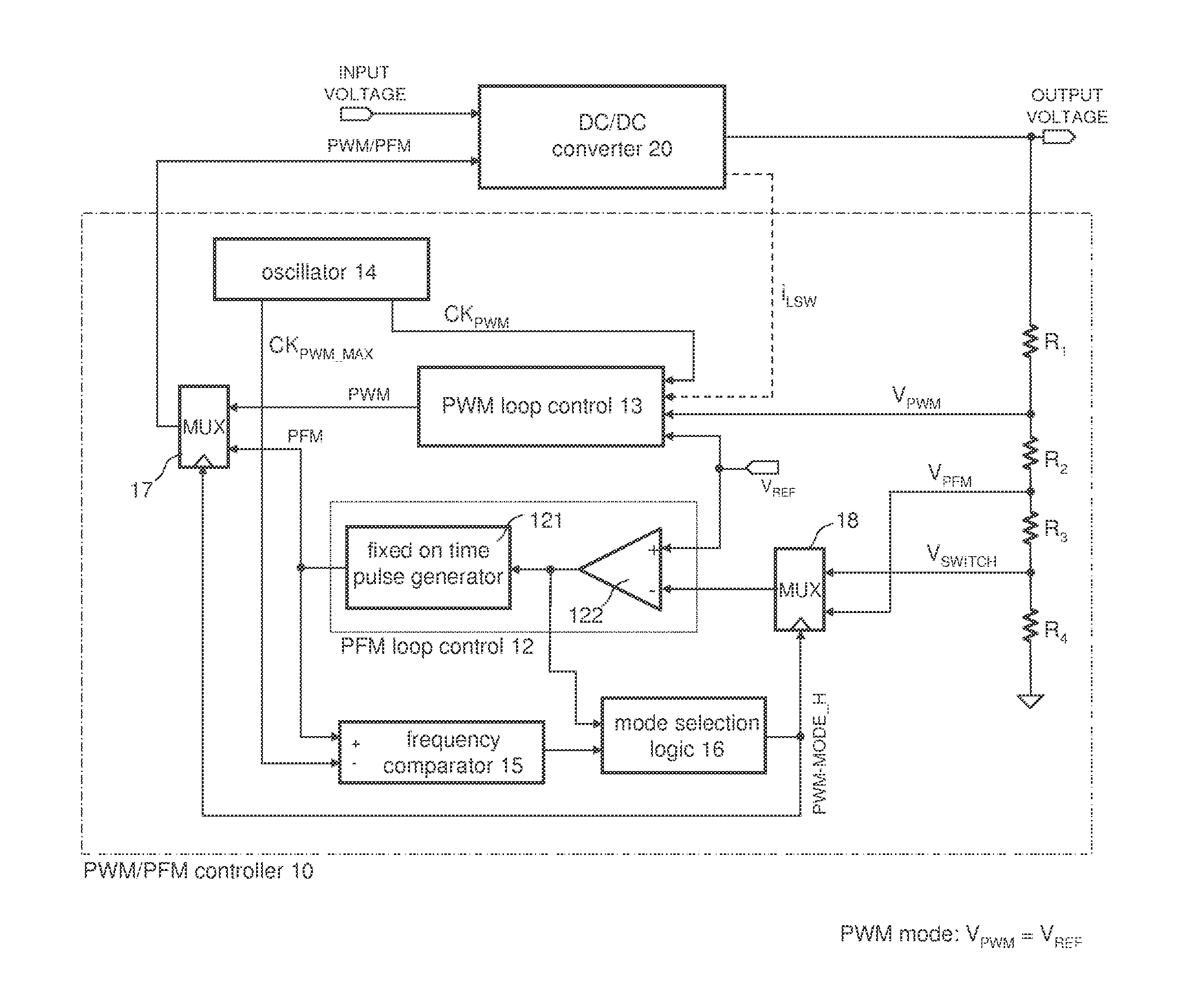
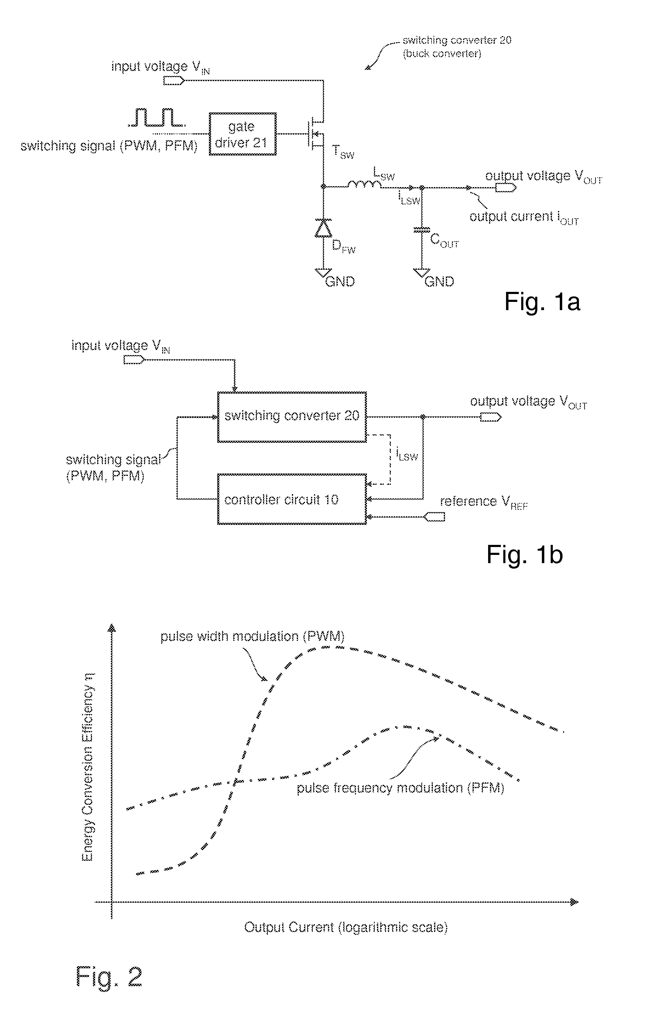
[0019]FIG. 1 a illustrates the topology of a common buck converter as one example of a switching converter. However, it should be noted that the present invention is not limited to switched mode power supplies (SMPS) including buck converters. The inventive concepts may be readily applied to any type of switching converter such as boost converters, buck-boost converters, Ćuk converters, flyback converters, etc. Generally a switching converter includes at least one switching element which are, in the present example of FIG. 1, a MOS transistor TSW and a free-wheeling diode DFW...


PUM


Abstract

A method for controlling a switching converter is disclosed whereby the switching converter is configured to convert an input voltage into an output voltage supplied to a load in accordance with a switching signal, The switching converter is configured to operate in a pulse width modulation mode or, alternatively, in a pulse frequency modulation mode. When operating in the pulse width modulation mode, generating, as the switching signal, a pulse width modulated (PWM) signal of a pre-defined constant switching frequency. The PWM signal has a duty cycle that is regulated such that the output voltage of the switching converter matches, at least approximately, a desired output voltage under the condition that the duty cycle being regulated such that it does not fall below a predefined minimum duty cycle. The output voltage is monitored and switched over to the pulse frequency modulation mode when the output voltage exceeds a predefined first threshold. The method further comprises, when operating in the pulse frequency modulation mode, monitoring the output voltage and generating, as the switching signal, a series of pulses of a predefined constant pulse length. A pulse is generated each time the output voltage falls to a predefined second threshold and monitoring the frequency of the switching signal and switching to the pulse width modulation mode when the frequency of the switching signal exceeds a predefined frequency threshold.

Description

TECHNICAL FIELD[0001]The present disclosure relates to the switching control of a switched mode power supply (SMPS) for ensuring an efficient operation thereof, in particular SMPS including control modes using either a pulse width modulation or a pulse frequency modulation for generating switching signals.BACKGROUND[0002]In recent years, stringent requirements concerning the efficiency of power supplies have brought attention to the use of Switching Mode Power Supplies (SMPS, also referred to as “switching converters”). However, the actual efficiency of an SMPS depends on the controller that determines the switching instants of the semiconductor switch(es) included in the SMPS. Probably the most common approach for controlling the switching of an SMPS is Pulse Width Modulation (PWM) which can implemented quite easily. However, using PWM for controlling an SMPS and thus for regulating its output voltage or output current does not guarantee a high efficiency over a wide range of outpu...

Claims


Application Information

Patent Timeline
Patent Type & Authority Applications(United States)
IPC IPC(8): G05F1/46
CPCH02M3/156Y02B70/16H02M2001/0032Y02B70/10H02M1/0032
Inventor GARBOSSA, CRISTIANFLAIBANI, MARCOVECCHIATO, ANDREAORIETTI, ENRICO
Owner INFINEON TECH AUSTRIA AG
Why Eureka
Try Eureka