Light source device, illumination device, and display device

a technology of illumination device and light source device, which is applied in the direction of lighting and heating apparatus, instruments, optical elements, etc., can solve the problems of not being able to obtain uniform illumination light all over the light output surface of the illumination device, and not being able to change the display device without changing, etc., to achieve uniform illumination light distribution

Inactive Publication Date: 2012-06-21
OPTO DESIGN INC
View PDF10 Cites 6 Cited by
  • Summary
  • Abstract
  • Description
  • Claims
  • Application Information

AI Technical Summary

Benefits of technology

[0016]It is an object of the present invention to provide a light source device and a display device that can prevent the adjacently connected portions from being darkened and can provide an illumination light having a uniform illuminance distribution as a whole, even if light from a point light source having high directionality is used and the point light sources are arranged on a convex curved surface or the like.MEANS FOR SOLVING THE PROBLEMS
[0043]With the display device of the present invention, a display device having a uniform illuminance distribution can be obtained, in which the adjacently connected portions of the light source devices are not darkened.

Problems solved by technology

An LED, however, is not suitable to be used without change in display devices or the like because of high directionality of light emitted therefrom.
The light source device described above, however, has had the following problem.
That is, a surface illumination light having a uniform illuminance distribution can be obtained when the light source device is used as a single unit, whereas when a plurality of such light source devices are adjacently connected to form a large-size surface illumination device, adjacently connected portions of the light source devices are dark, and thus it is impossible to obtain an illumination light that is uniform all over a light output surface of the illumination device.

Method used


Image

  • Light source device, illumination device, and display device
  • Light source device, illumination device, and display device
  • Light source device, illumination device, and display device

Examples


first embodiment

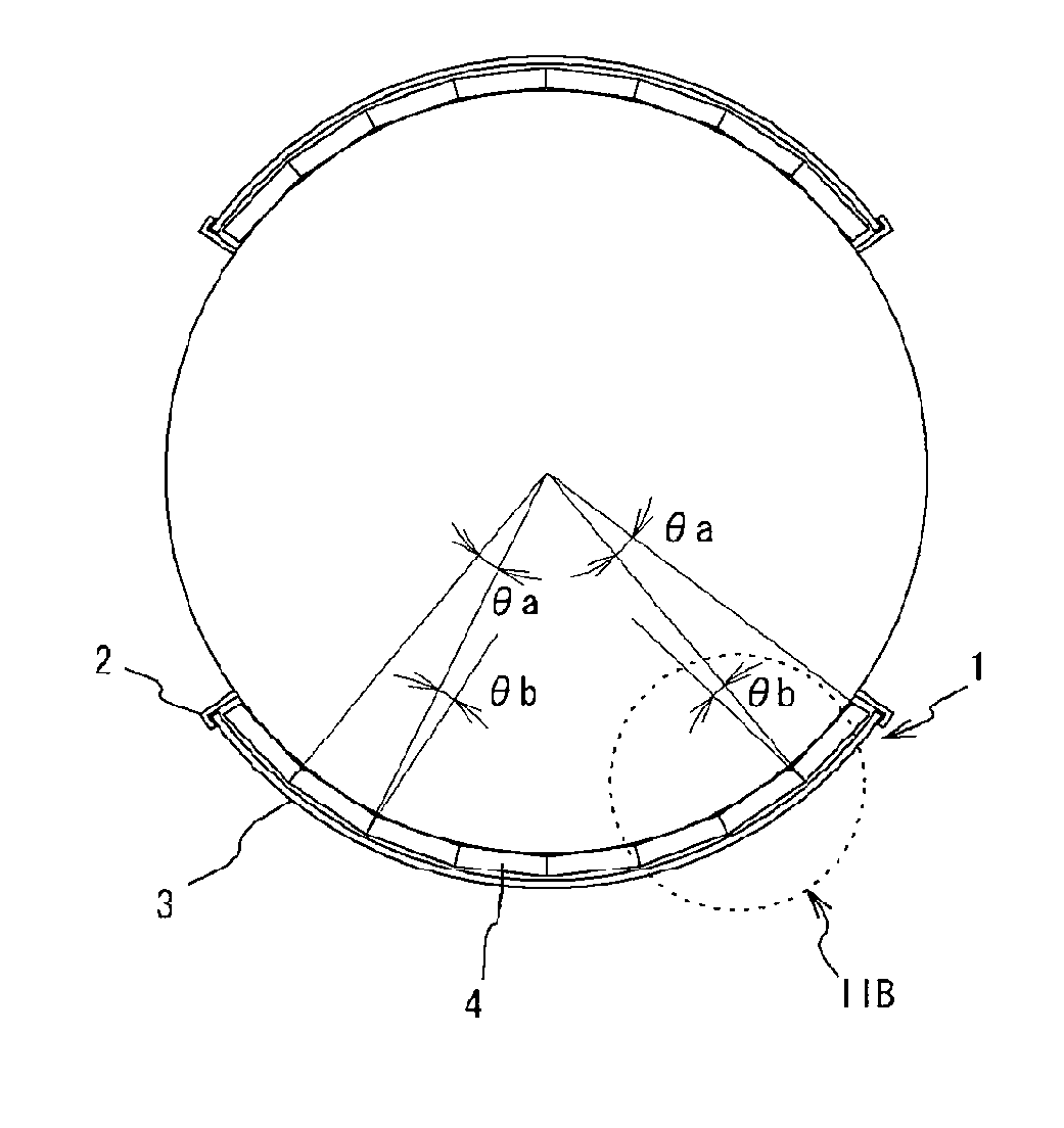
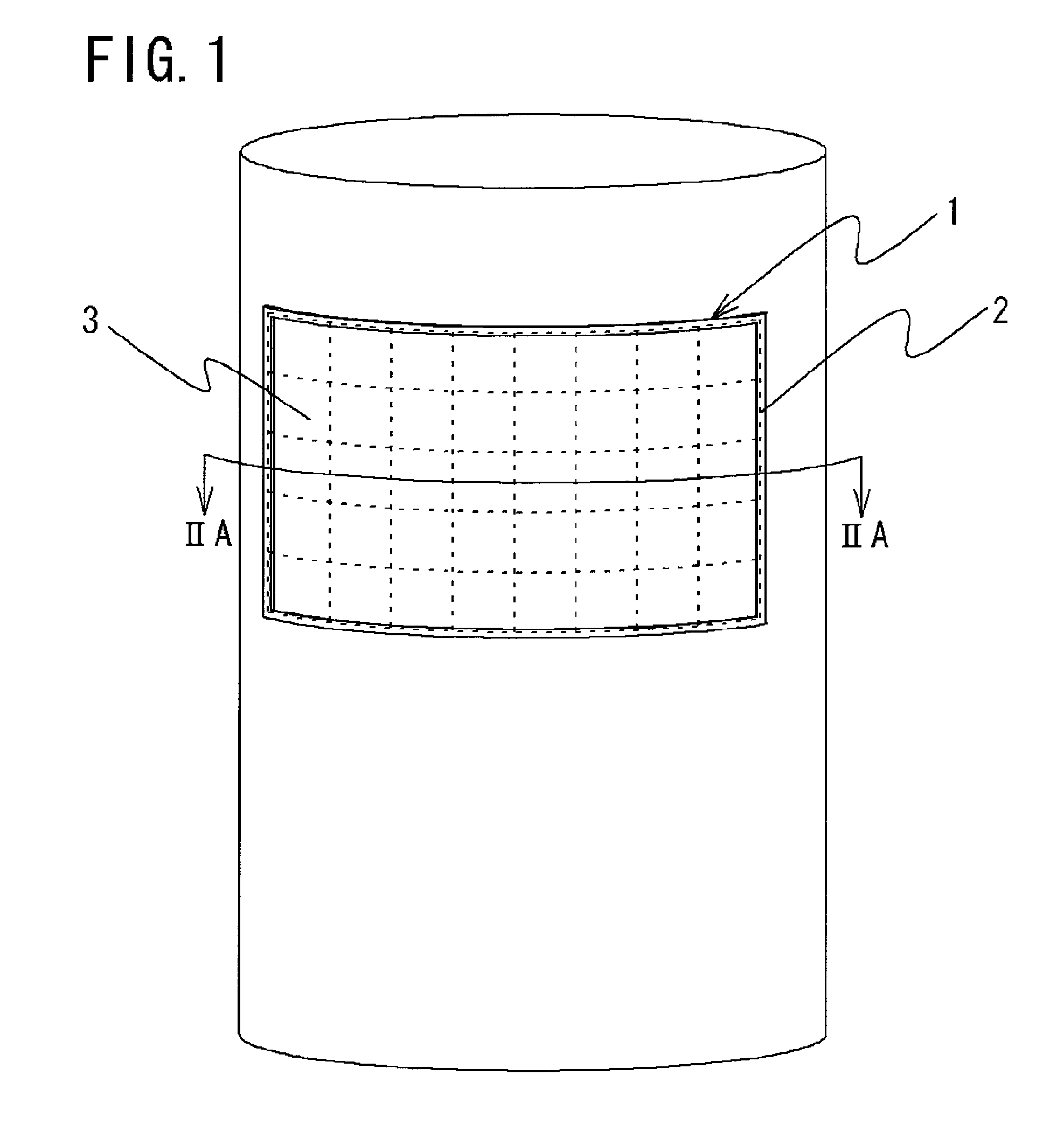
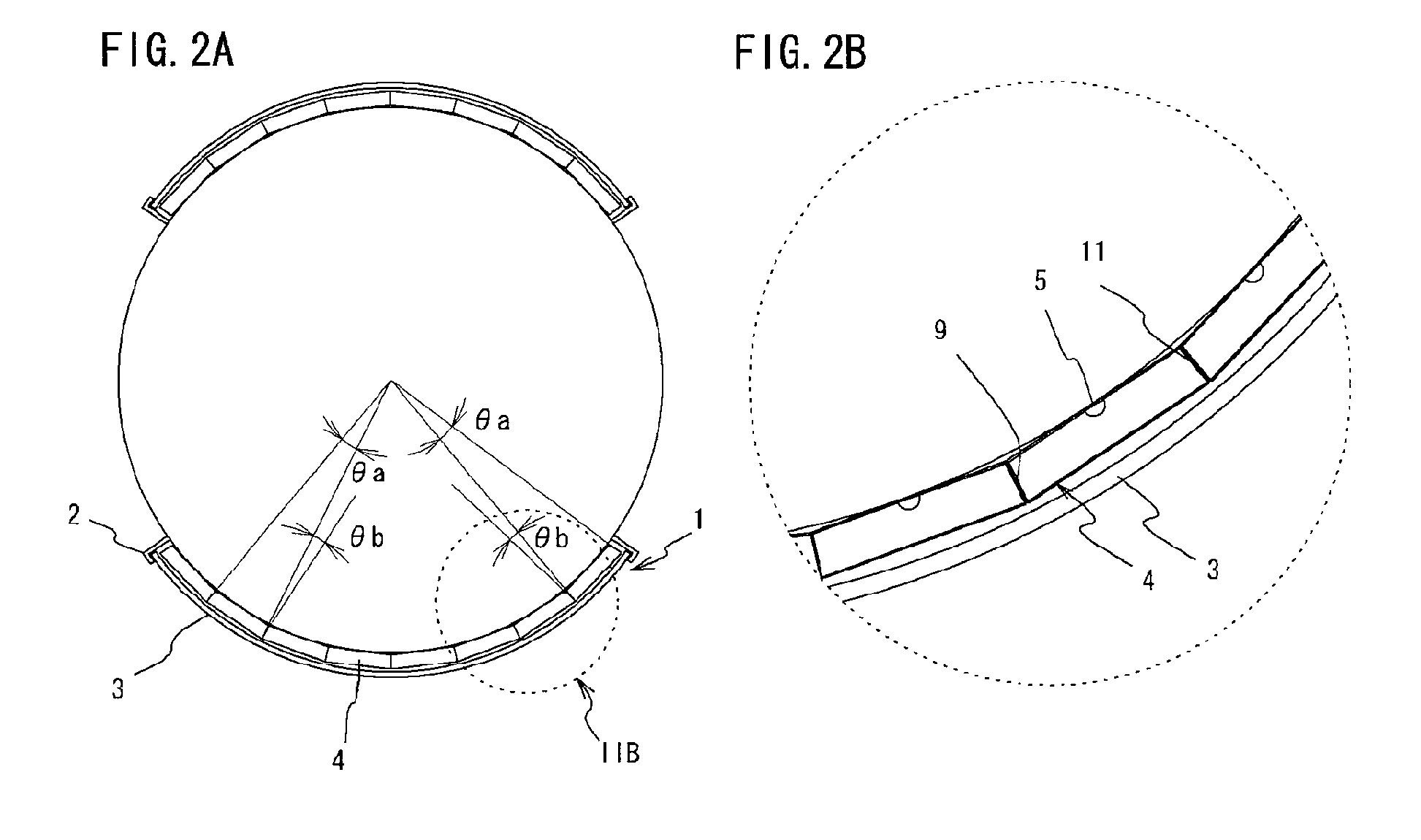
[0059]An illumination device according to a first embodiment of the present invention will be described using FIGS. 1 and 2. FIG. 1 is a perspective view of the illumination device according to the first embodiment of the present invention. FIG. 2A is a cross-sectional view of the illumination device, taken on line IIA-IIA of FIG. 1, and FIG. 2B is a partial enlarged view of FIG. 2A.

[0060]As illustrated in FIGS. 1 and 2, an illumination device 1 is composed of a frame 2 installed on a convex curved surface such as a side face of a cylinder, a diffusion plate 3 inserted in an opening of the frame 2, and a plurality of light source devices 4 arranged in an adjacently connected manner inside the frame.

[0061]The frame 2 is formed of metallic sheet material or a plastic molded body, and has a shape fitting along the convex curved surface such as a side face of a cylinder. The diffusion plate 3 is inserted in the opening of the frame 2. The diffusion plate 3 need only be made of material ...

second embodiment

[0078]An illumination device according to a second embodiment of the present invention will be described using FIG. 8. Each of FIGS. 8A and 8B is a cross-sectional view of the illumination device according to the second embodiment of the present invention corresponding to FIG. 2A.

[0079]The illumination device according to the second embodiment of the present invention is structured to have one light source device arranged at each one of sidewall surfaces of a polygonal column, and a cylindrical diffusing plate provided outside of the light source devices. As illustrated in FIG. 8A, an illumination device 1A is arranged with one light source device 4A in each direction perpendicular to a height direction of a quadrangular column, and sidewall portions of the light source devices 4A are adjacently connected so as to be in contact with each other. That is, in a transverse plane of the illumination device 1A, four of the light source devices 4A are adjacently connected. Note that one or...

third embodiment

[0082]An illumination device according to a third embodiment of the present invention will be described using FIGS. 9 to 11. FIG. 9 is a front view illustrating a state in which the illumination device according to the third embodiment is installed on a cylinder. FIG. 10 is a perspective view of a light source device constituting the illumination device of FIG. 9. FIG. 11 is an exploded perspective view of the light source device of FIG. 10.

[0083]The illumination device according to the third embodiment of the present invention has a different structure in the light source device from that of the first embodiment, but the other parts are common. Therefore, the same reference numerals are used for the common parts, and descriptions thereof will be omitted.

[0084]As illustrated in FIG. 9, an illumination device 1C is composed of a frame 2 installed on a convex curved surface such as a side face of a cylinder, a diffusion plate 3 inserted in an opening of the frame 2, and a plurality of...


PUM


Abstract

Disclosed is a light source device (4) capable of being used by adjacently connecting with each other in multiple, the light source device includes: a point light source (5) having high directionality; a box-shaped housing (6) having a bottom to center of which the point light source is fixed, sidewall portions arranged in a standing manner from edges of the bottom up to a predetermined height, a side portion defining an opening provided facing the point light source, and a reflection member forming an inner wall surface of the housing; and a transmissive / reflective plate covering the opening of the housing and being fixed at a circumference thereof to edges of the opening of the housing. At least one of the sidewall portions that is in contact with a sidewall portion of another light source device is arranged in a standing manner at an angle θ, where 90°<θ≦150°, relative to the bottom, and is provided with a light-transmitting hole on the side of the opening of the housing.

Description

TECHNICAL FIELD[0001]The present invention relates to a light source device, an illumination device, and a display device, and more in detail, to a light source device, an illumination device, and a display device that can provide an illumination light having a uniform illuminance distribution with light from a point light source, even if the point light source have high directionality and are used as light sources arranged on a convex curved surface such as an outer wall surface of a cylinder.BACKGROUND ART[0002]In recent years, there are increasing examples of advertisements provided on surfaces of cylinders placed in spaces such as railway station yards and underground shopping malls. Although these advertisements have previously been mainly displayed as posters, there are also increasing examples of internally illuminated signs installed in a manner surrounding the cylinders.[0003]In recent years, research and development of light-emitting diode (hereinafter called “LED”) have r...

Claims


Application Information

Patent Timeline
Patent Type & Authority Applications(United States)
IPC IPC(8): F21V7/00
CPCG02B6/0021G02B6/0036G02B6/0073G02F1/133611G02F1/13336G02F1/133603G02B6/0096
Inventor SATO, EIICHIFUKUOKA, KENJISATO, HIROYASU
Owner OPTO DESIGN INC
Why Eureka
Try Eureka