
Universal Subsea Oil Containment System and Method

a technology of oil containment system and subsea oil, applied in the field of oil and gas systems, can solve the problems of life loss, limited solutions, and roughly thirty-year technology gap that exists

Inactive Publication Date: 2012-06-21
CARTER GEORGE +1
View PDF6 Cites 37 Cited by
  • Summary
  • Abstract
  • Description
  • Claims
  • Application Information

AI Technical Summary

Benefits of technology

"The present invention is about an apparatus and method for containing oil and gas leaking from underwater man-made structures. The apparatus includes a conduit and a containment tank with valves for metering liquid and gas flow. The conduit is positioned over the leaking structure and liquid and gas flow upward through the interior of the conduit. The method involves closing valves within the conduit, injecting a gas into the interior, positioning the conduit over the leaking structure, opening valves to meter liquid and gas, and pumping out liquid from the upper portion of the conduit to induce an upward flow of fluids. The technical effect of this invention is to provide a way to contain oil and gas leaks from underwater man-made structures, reducing the risk of environmental damage and pollution."

Problems solved by technology

However, with the use of deepwater drilling, there have been several problems.
One such problem occurred in 2010 with the Macondo well blowout in the Gulf of Mexico which caused the destruction of the Deepwater Horizon rig, sadly resulting in loss of life, and was the source of the largest offshore oil spill in U.S. history.
The BP oil spill exposed the roughly thirty-year technology gap that exists in current methods to cleanup and contain an offshore oil spill, particularly in ultra-deepwater.
Currently, when a wellhead leaks oil and gas, there are limited solutions for alleviating or terminating the leak at deep depths of seawater.

Method used


Image

  • Universal Subsea Oil Containment System and Method
  • Universal Subsea Oil Containment System and Method
  • Universal Subsea Oil Containment System and Method

Examples


Embodiment Construction

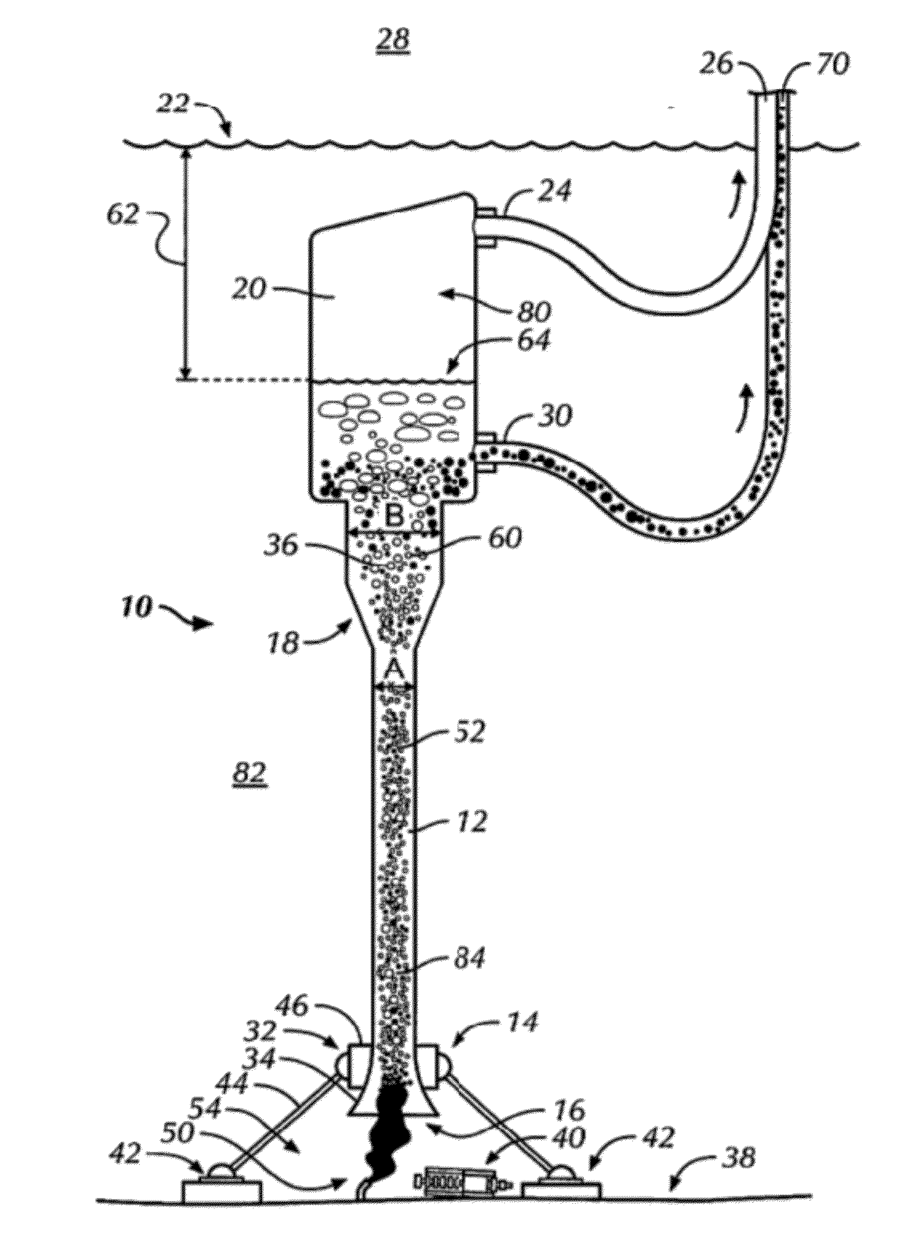
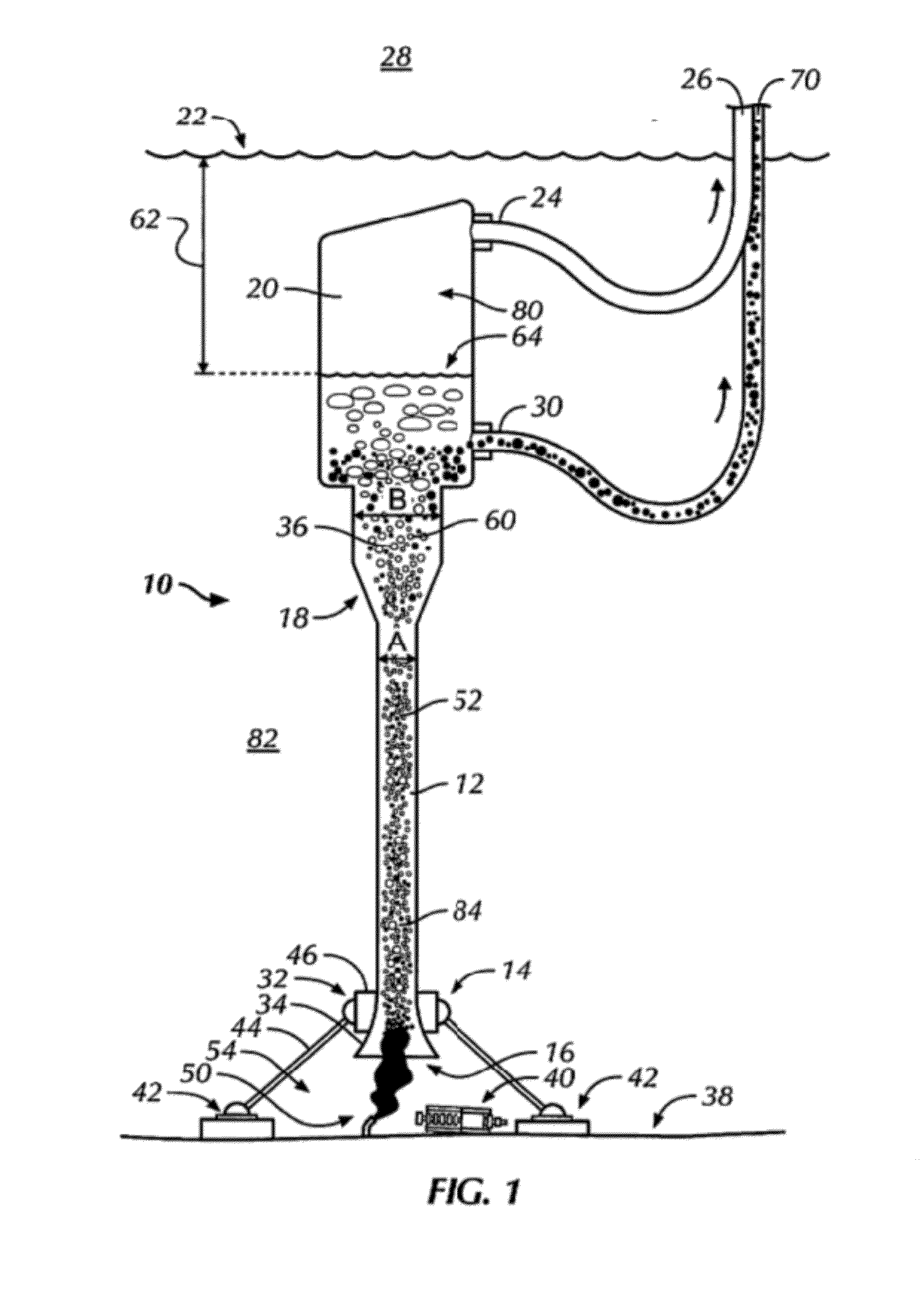
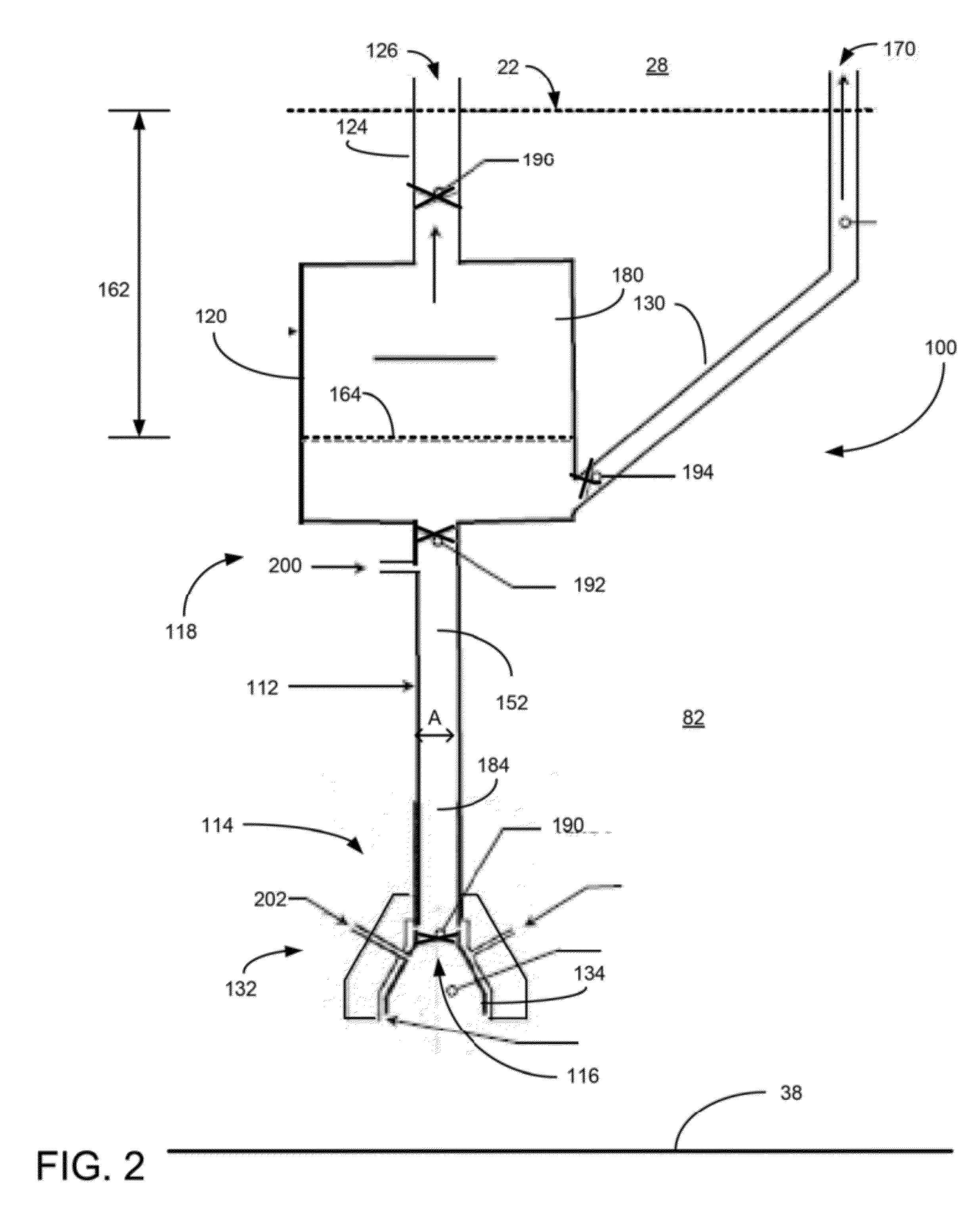
[0017]The present invention is a system and method of capturing and containing oil and gas leaking from an underwater man-made structure. FIG. 1 is a side view of a containment system 10 in one embodiment of the present invention. The containment system 10 includes a main conduit 12 having a first lower end 14 with an opening 16 and an opposite second upper end 18 with a containment tank 20. In one embodiment, the containment tank may be located below a seawater surface 22. In this embodiment, the containment tank may be coupled to a gas release tube 24 leading to the surface 22. The tube 24 may lead to an aperture 26 opened to the outside above-water environment 28 or to a man-made structure such as a ship (not shown). Flow control devices, such as fixed (e.g., Venturi) or variable (e.g., valves) may be used to control the flow of the gas exiting the tube. The containment tank may also include a second liquid ejection tube 30 having a pump (not shown) leading to the surface 22 and ...


PUM


Abstract

A system, method, and apparatus for containing oil and gas leaking from an underwater wellhead or other man-made structure. The apparatus includes a conduit having an upper end and a lower end with an opening. The conduit is sized for the lower end to be positioned over a plume leaking from the man-made structure and the upper end to be substantially near or at the seawater surface. The apparatus also includes a port for introducing a suitable gas such as nitrogen into the interior of the conduit for displacing seawater from the interior of the conduit. In addition, the apparatus includes a plurality of valves for metering liquid and gas flow within the interior of the conduit. The conduit is positioned over the leaking man-made structure and oil and gas flow upward from the leaking man-made structure through the interior of the conduit.

Description

RELATED APPLICATIONS[0001]This utility application is a continuation-in-part application of co-pending U.S. patent application Ser. No. 13 / 162,666 entitled “Universal Subsea Oil Containment System and Method” filed on Jun. 17, 2011 under the name of George Carter which claims the benefit of U.S. Provisional Patent Application Ser. No. 61 / 358,697 filed Jun. 25, 2010 and is hereby incorporated by reference.BACKGROUND OF THE INVENTION[0002]1. Field of the Invention[0003]This invention relates to oil and gas systems. Specifically, and not by way of limitation, the present invention relates to a system and method in some scenarios, however, there are blowout scenarios were leaks develop outside the well casing, or leaks develop from the BOP or a damaged connector. Ideas have arisen to “drop” a containment device over the source of the spill, but containment domes have had limited success in shallow seawater and have never worked in deepwater environments. A dome-like design, with the ope...

Claims


Application Information

Patent Timeline
Patent Type & Authority Applications(United States)
IPC IPC(8): E02B15/00
CPCE21B43/0122E02B2015/005
Inventor CARTER, GEORGEVOLK, MICHAEL
Owner CARTER GEORGE
Learn More