Helicopter rotor control system

a technology of rotor control system and helicopter, which is applied in the field of helicopter rotor control system, can solve the problems of heavy diameter rods, difficult packaging within the upper rotor control shaft, and the upper rotor control system is typically more complex

Active Publication Date: 2012-06-21
SIKORSKY AIRCRAFT CORP
View PDF2 Cites 30 Cited by
  • Summary
  • Abstract
  • Description
  • Claims
  • Application Information

AI Technical Summary

Benefits of technology

[0010]FIG. 3 is a partial perspective view of a c

Problems solved by technology

The upper rotor control system is typically more complex and utilizes an upper rotor control shaft mounted through the lower rotor shaft

Method used


Image

  • Helicopter rotor control system
  • Helicopter rotor control system
  • Helicopter rotor control system

Examples


Embodiment Construction

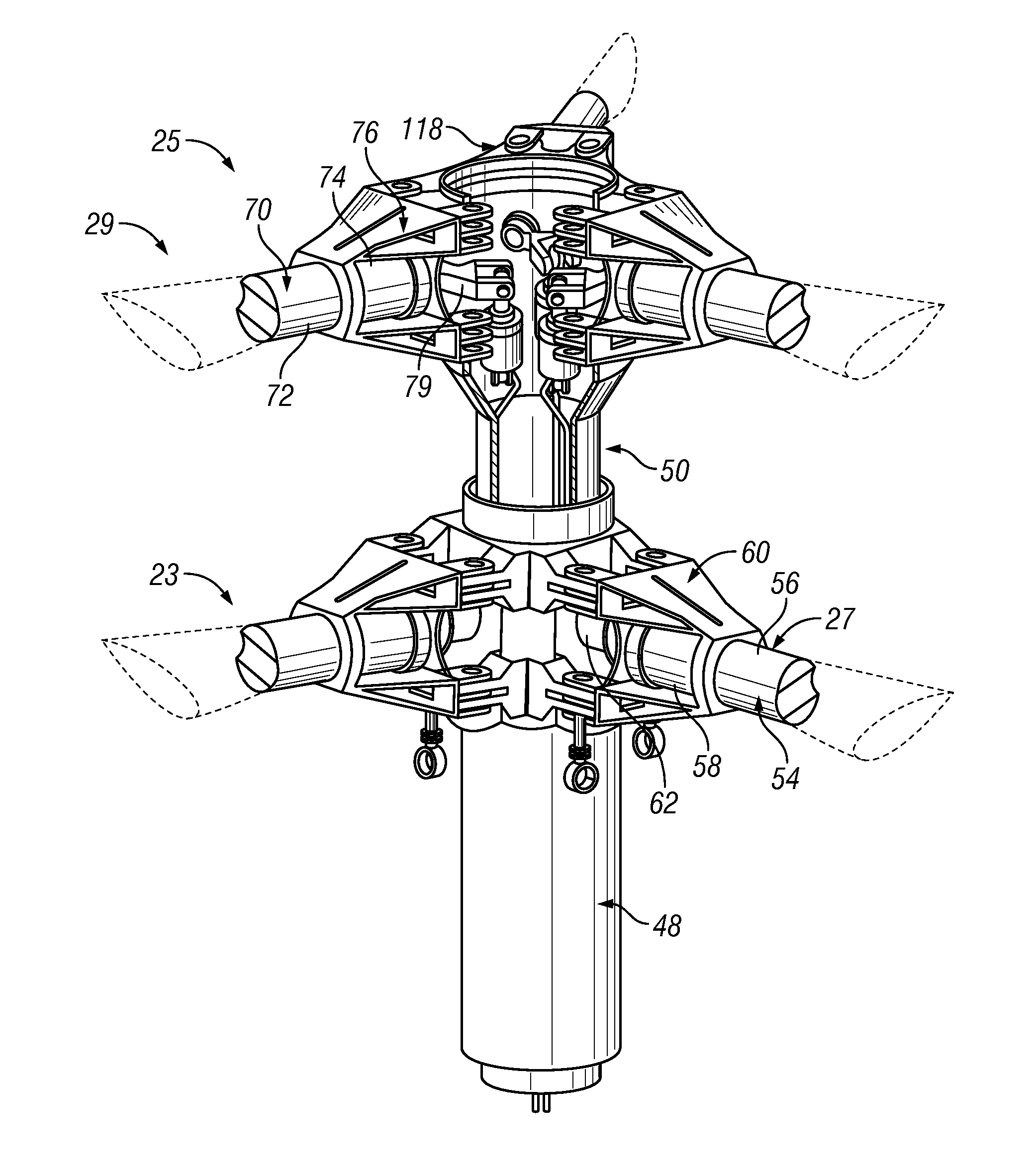
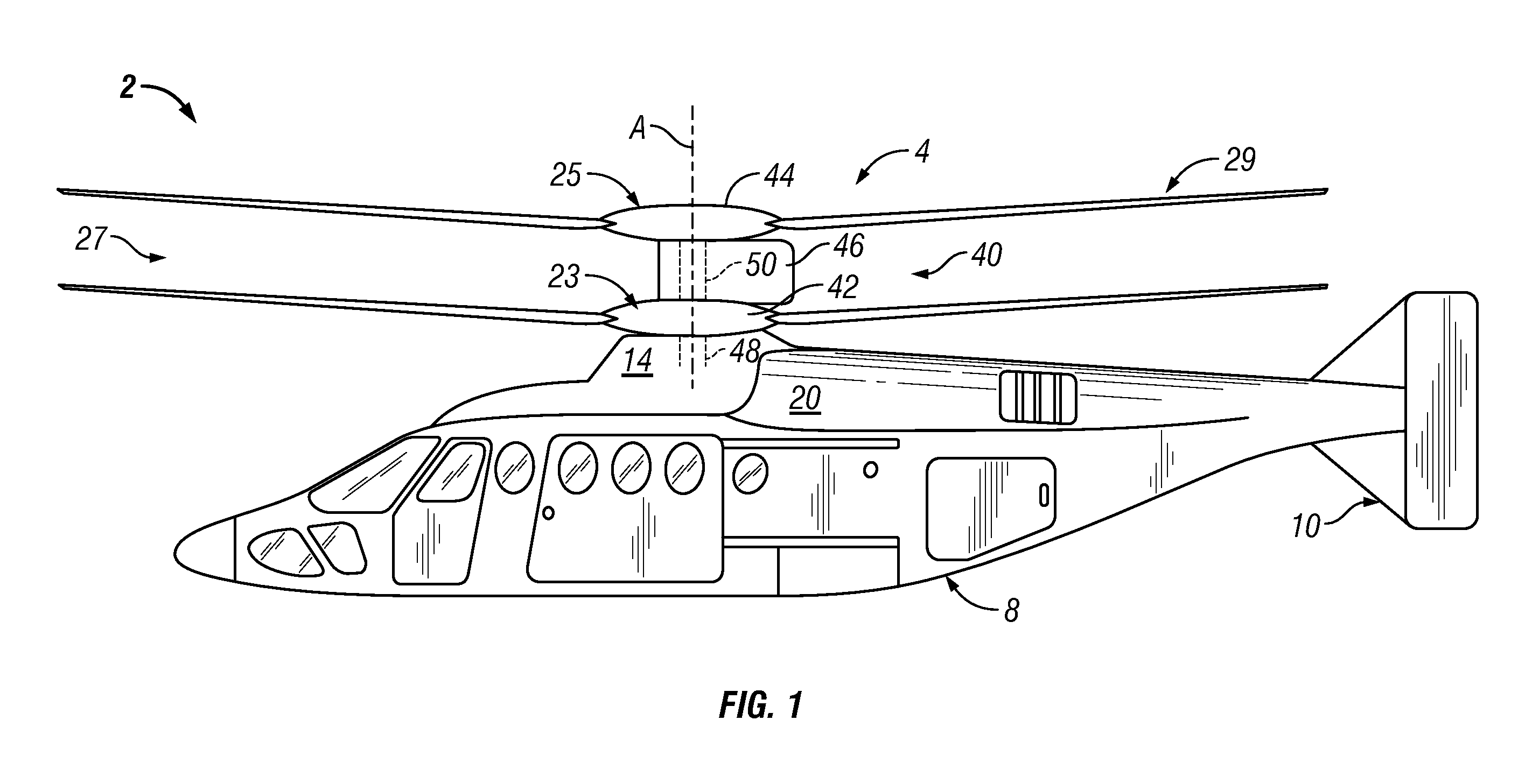
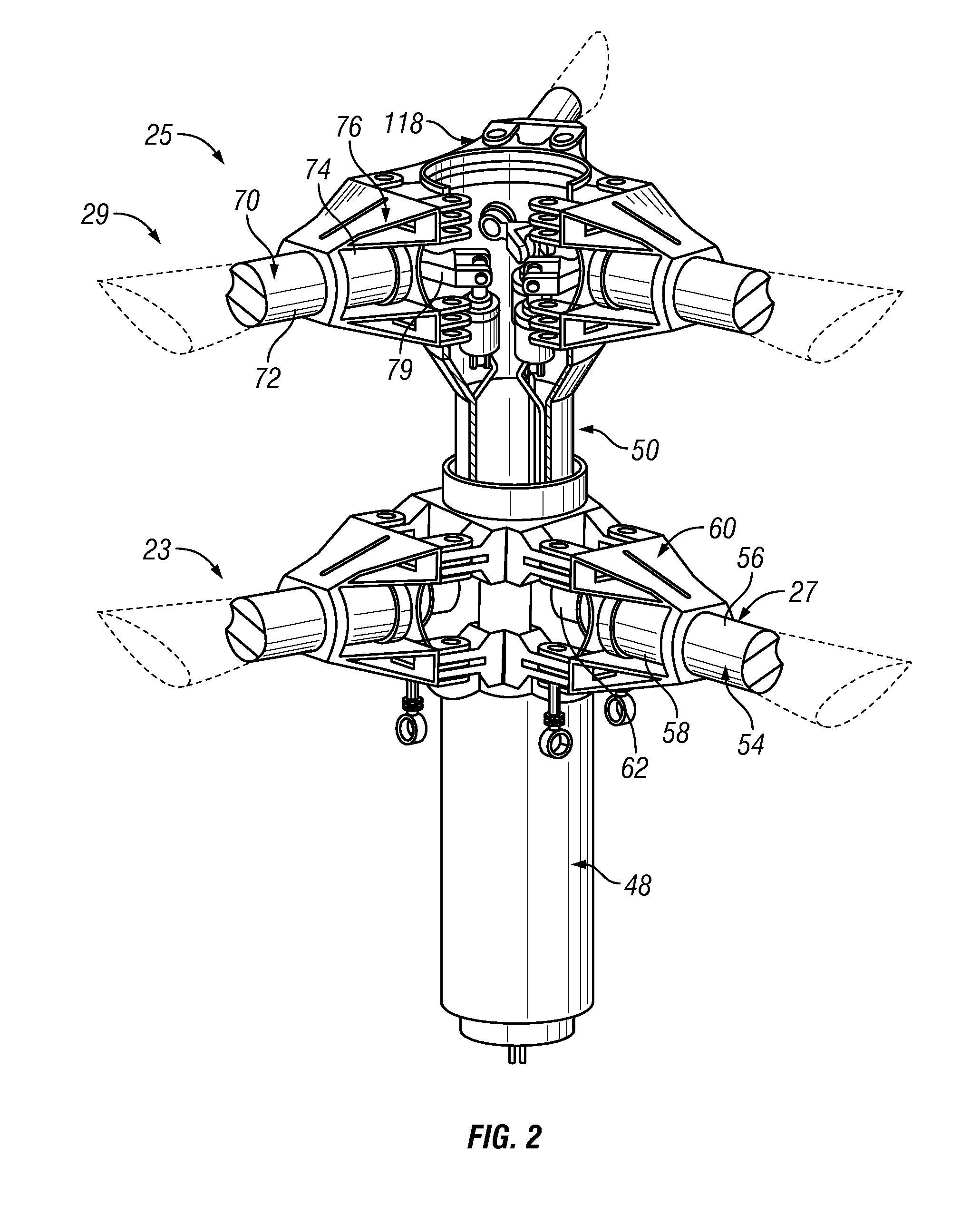
[0012]With reference to FIG. 1, a vertical take off and landing (VTOL) rotary-wing aircraft constructed in accordance with an exemplary embodiment is indicated generally at 2. Rotary-wing aircraft 2 includes a dual, counter-rotating, coaxial rotor system 4 that rotates about an axis of rotation A. Rotary-wing aircraft 2 includes an airframe 8 as well as an optional translational thrust system 10. Translational thrust system 10 provides translational thrust generally parallel to an aircraft longitudinal axis (not separately labeled). Although a particular aircraft configuration is illustrated in the disclosed embodiment, other rotary-wing aircraft including aircraft having both dual and single rotor systems will also benefit from the present invention.

[0013]Further illustrated in FIG. 1, rotary-wing aircraft 2 includes a main gear box 14 which, in accordance with the exemplary embodiment shown, is located above the aircraft cabin. Main gear box 14 is configured to drive rotor system ...


PUM


Abstract

A rotor control system operatively linked to a plurality of rotor blades includes a swashplate assembly having a stationary member and a rotating member. A blade attachment member is operatively connected to the plurality of rotor blades and a control horn is operatively connected to the blade attachment member and one of the plurality of rotor blades. At least one hydraulic actuator member is operatively coupled to the control horn and at least one hydraulic actuator element is operatively coupled to the swashplate assembly and the at least one hydraulic actuator member. The at least one hydraulic actuator member transmits control signals from the swashplate assembly to the one of the plurality of rotor blades through the at least one hydraulic actuator member.

Description

BACKGROUND OF THE INVENTION[0001]The subject matter disclosed herein relates to the art of helicopters and, more specifically, to a helicopter rotor control system.[0002]Control of rotary-wing aircraft is effected by rotor blade pitch variations. Rotor blades are controlled individually (cyclic control) and collectively (collective control). Main rotor pitch control is typically achieved through a swashplate assembly that transfers motion of non-rotating control members to rotating control members. The swashplate assembly is typically concentrically mounted about a rotor shaft. A typical swashplate assembly includes two rings connected by a series of bearings. One ring is mounted to the aircraft (stationary) and another ring is mounted to a hub portion of the rotor shaft (rotating). Movements in the stationary ring are transferred to the rotating ring to control blade pitch.[0003]Rotary-wing aircraft having dual or counter-rotating rotor blade systems require both an upper rotor con...

Claims


Application Information

Patent Timeline
IPC IPC(8): F04D29/36F04D27/00
CPCB64C27/10B64C27/12Y02T50/34B64C2027/7216B64C27/32Y02T50/30
Inventor COWLES, DEVON
Owner SIKORSKY AIRCRAFT CORP
Why Eureka
Try Eureka